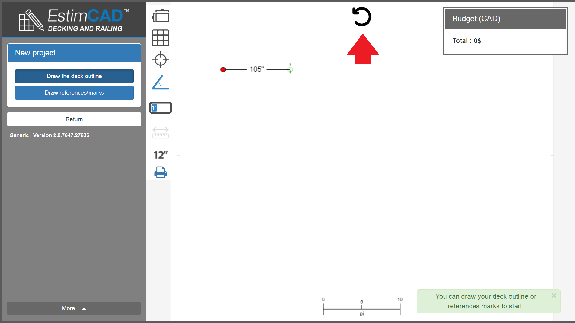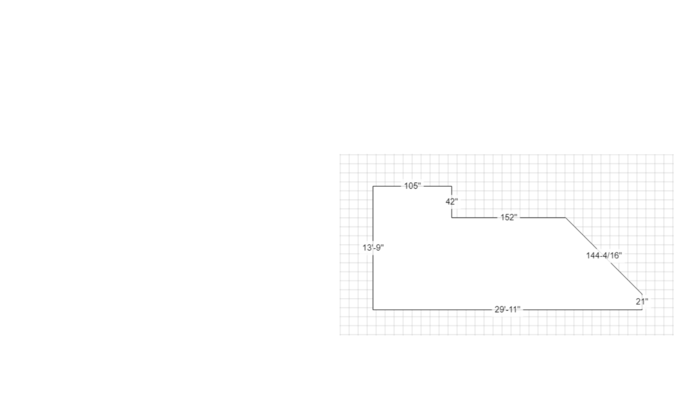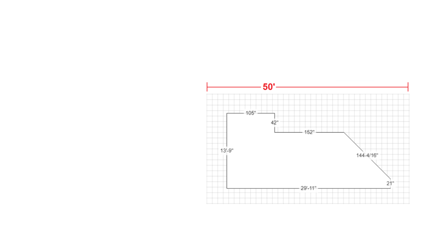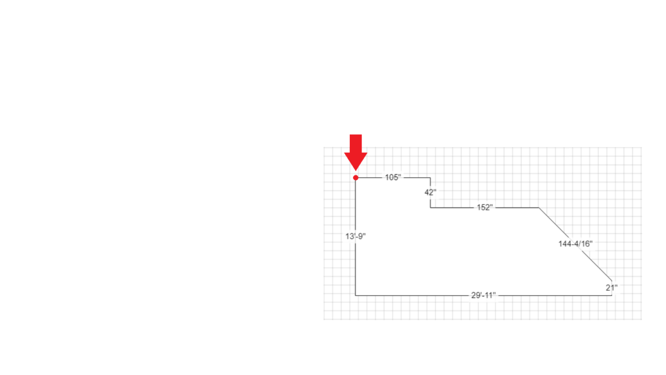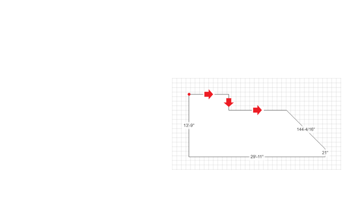
Click on the left or right arrows to move from one image to another to learn what measurements are required to calculate your complete deck.
Introducing the new EstimCAD ™ Deck and Railings application that allows
novice, intermediate and advanced users to draw and estimate simple and
complex patio plans.
This training guide will allow users to learn how to draw a plan, create
and place stairs and railings. Then the calculations will be displayed
automatically and instantly throughout the estimation process.
BROWSER
Use only the Google Chrome ™ browser to estimate a plan because the
application has not yet been tested with other browsers.
TO CONTACT US
We invite you to contact us with any questions and comments at :
support@estimcad.com
Here are three (7) slideshows that will help the user to visualize the basics required to learn how to draw and estimate a deck and railing plan. At the same time, it is suggested to do a practical exercise. So just reproduce the plan (to print). This will allow you to get started more quickly, using the application.
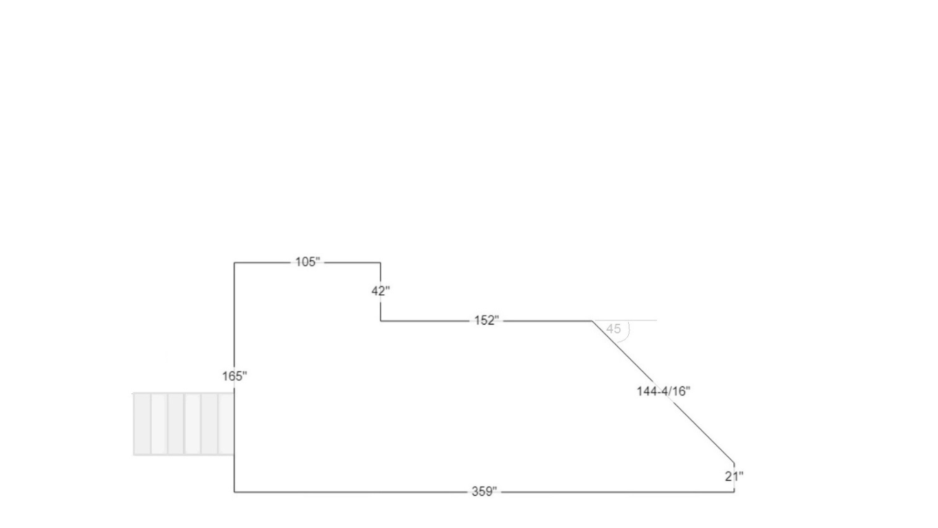
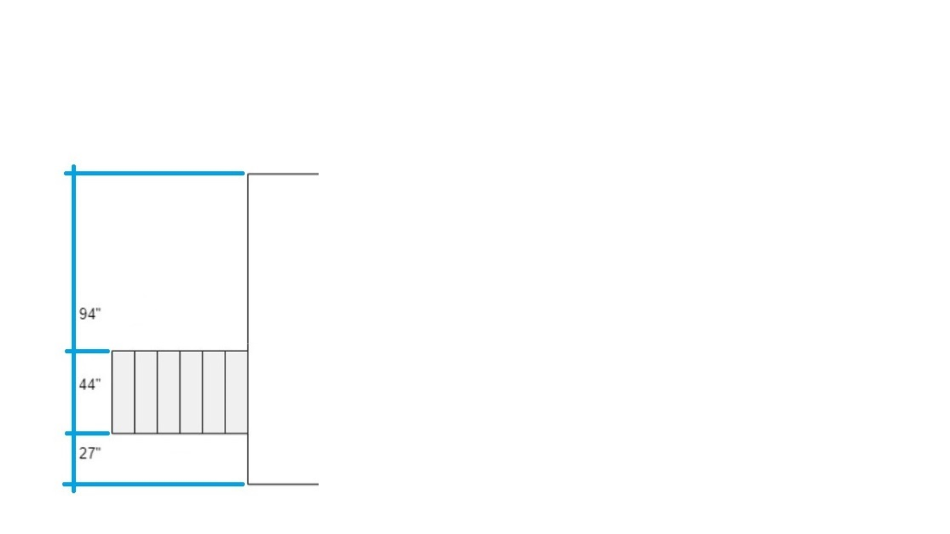
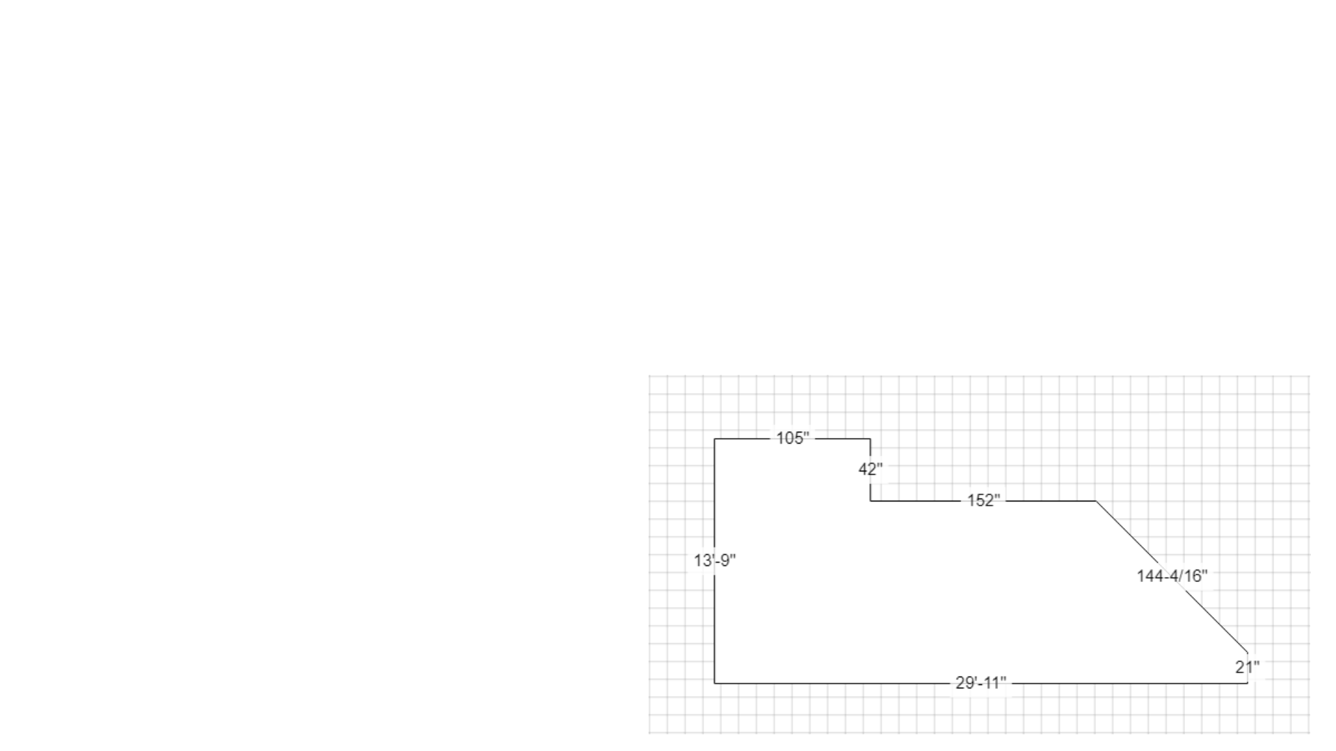
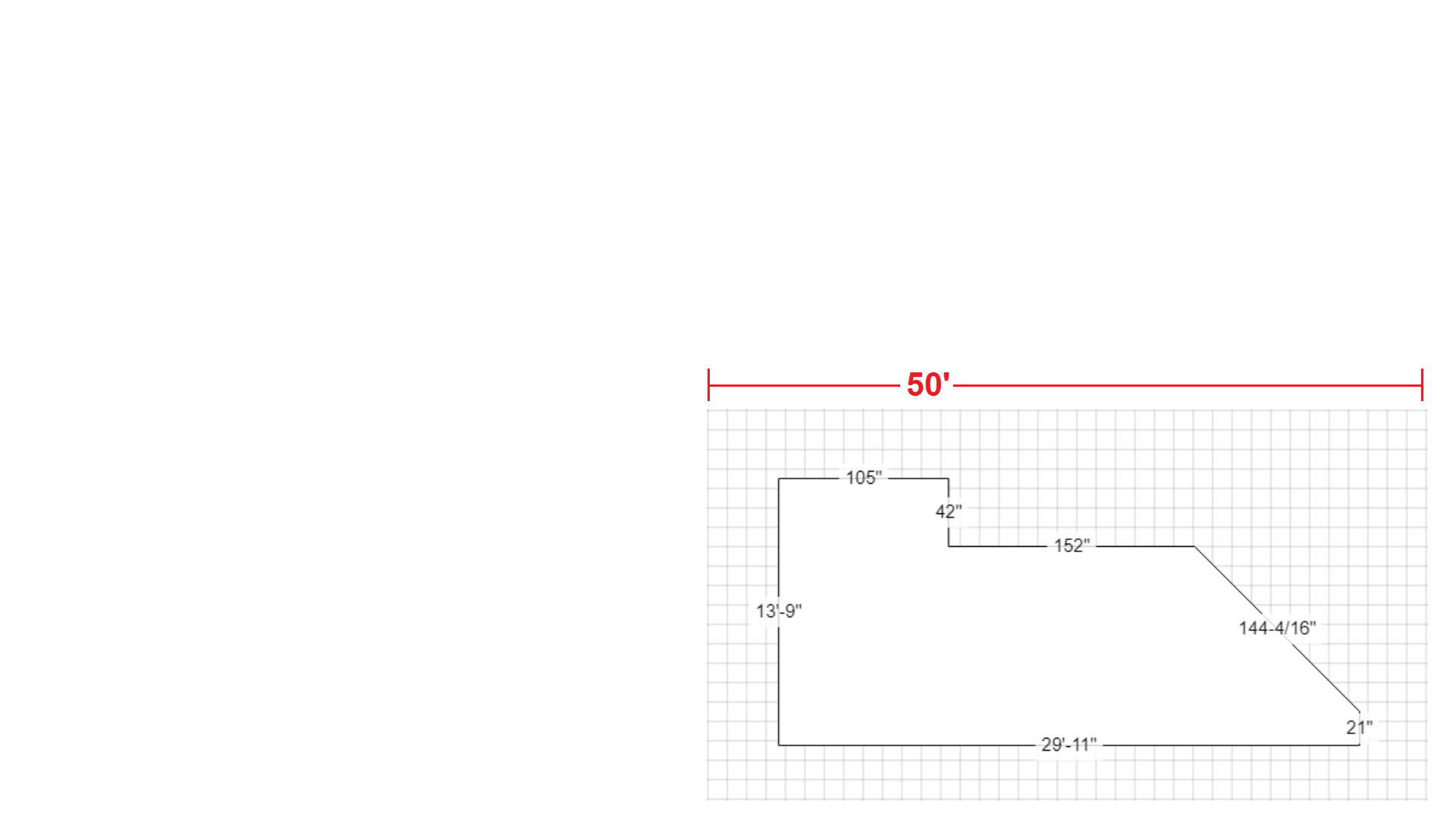
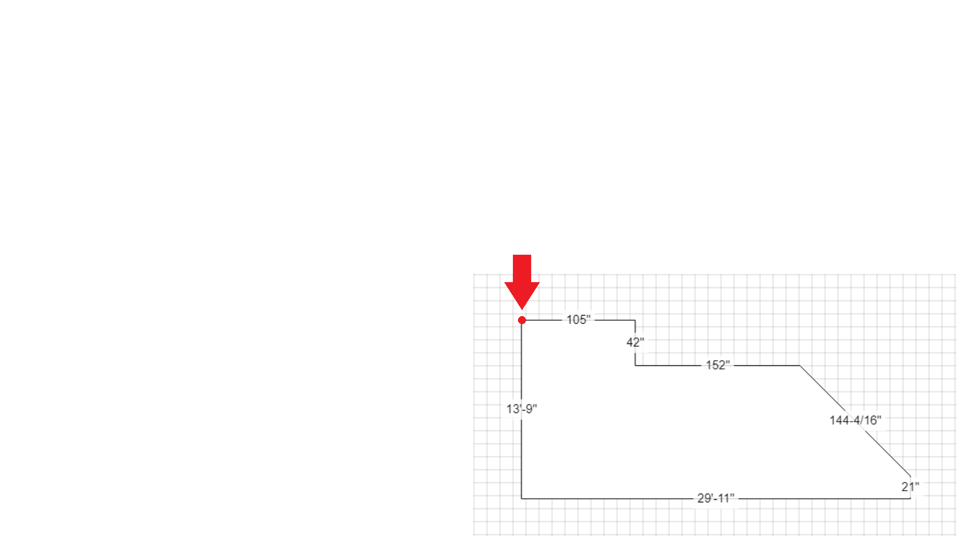
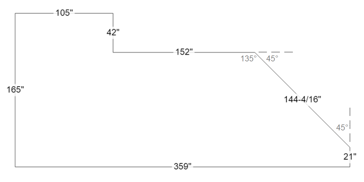
Before starting to draw a plan, it is important to identify and take all the precise measurements of the outline of a deck and the stairs that will have to be reproduced by drawing the perimeter of a plan.
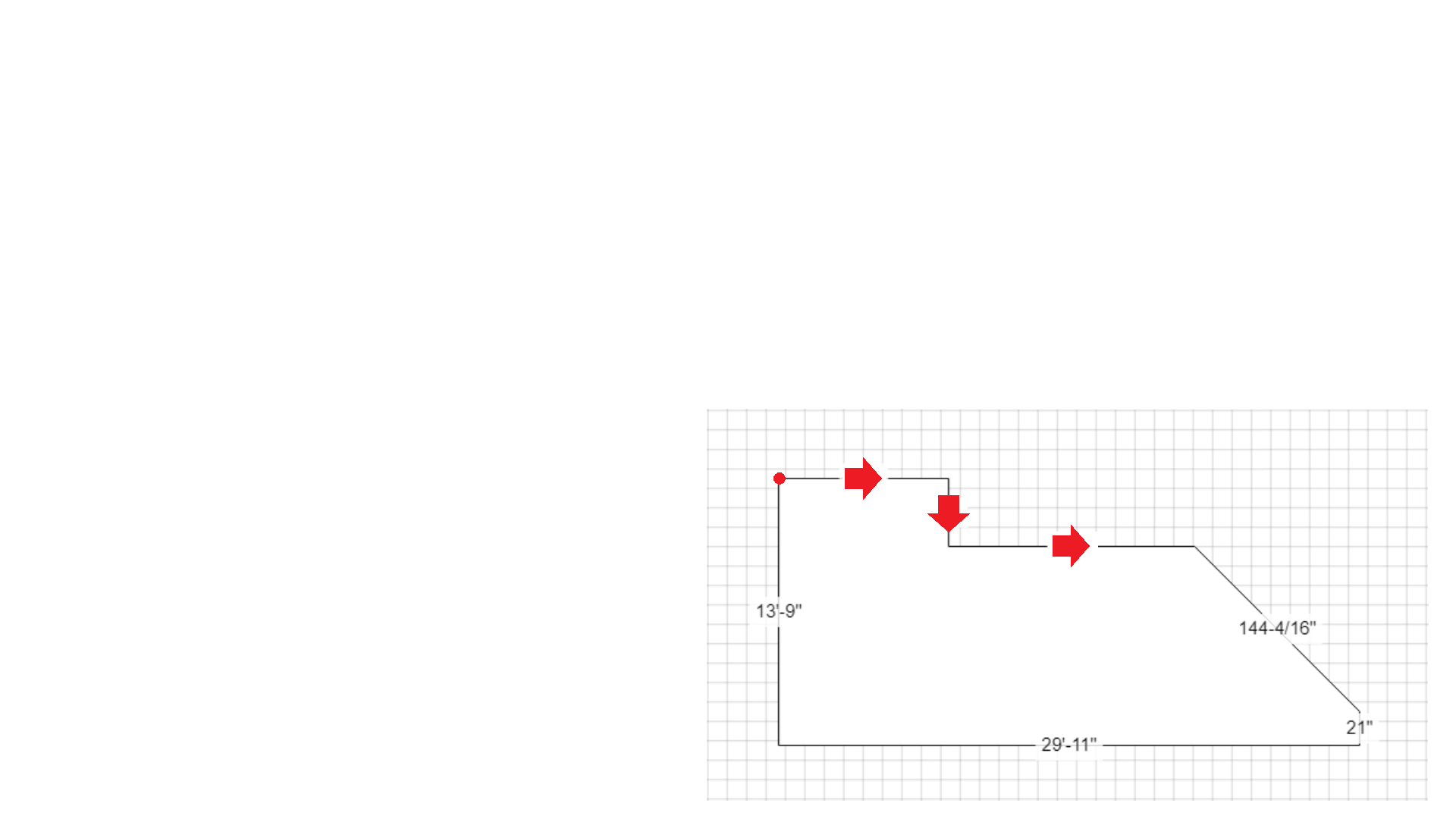
The first basic notion is that of learning to draw a patio perimeter using a mouse and to perform a complete layout of
the plan by connecting the last point to the first point, as illustrated in the following slide show.

The second basic concept is to create a stairs around the perimeter of a deck plan, as shown in the following slideshow.

The third basic notion is to create and place the railing on the outlines of a deck plan and its stairs, as illustrated in the following slideshow.

This function allows you to draw a plan using the numeric keypad which is often adopted by intermediate users but can also be used by experienced beginners. Previously, print this plan and then practice drawing it with a keyboard by following the steps as illustrated in the slideshow below.
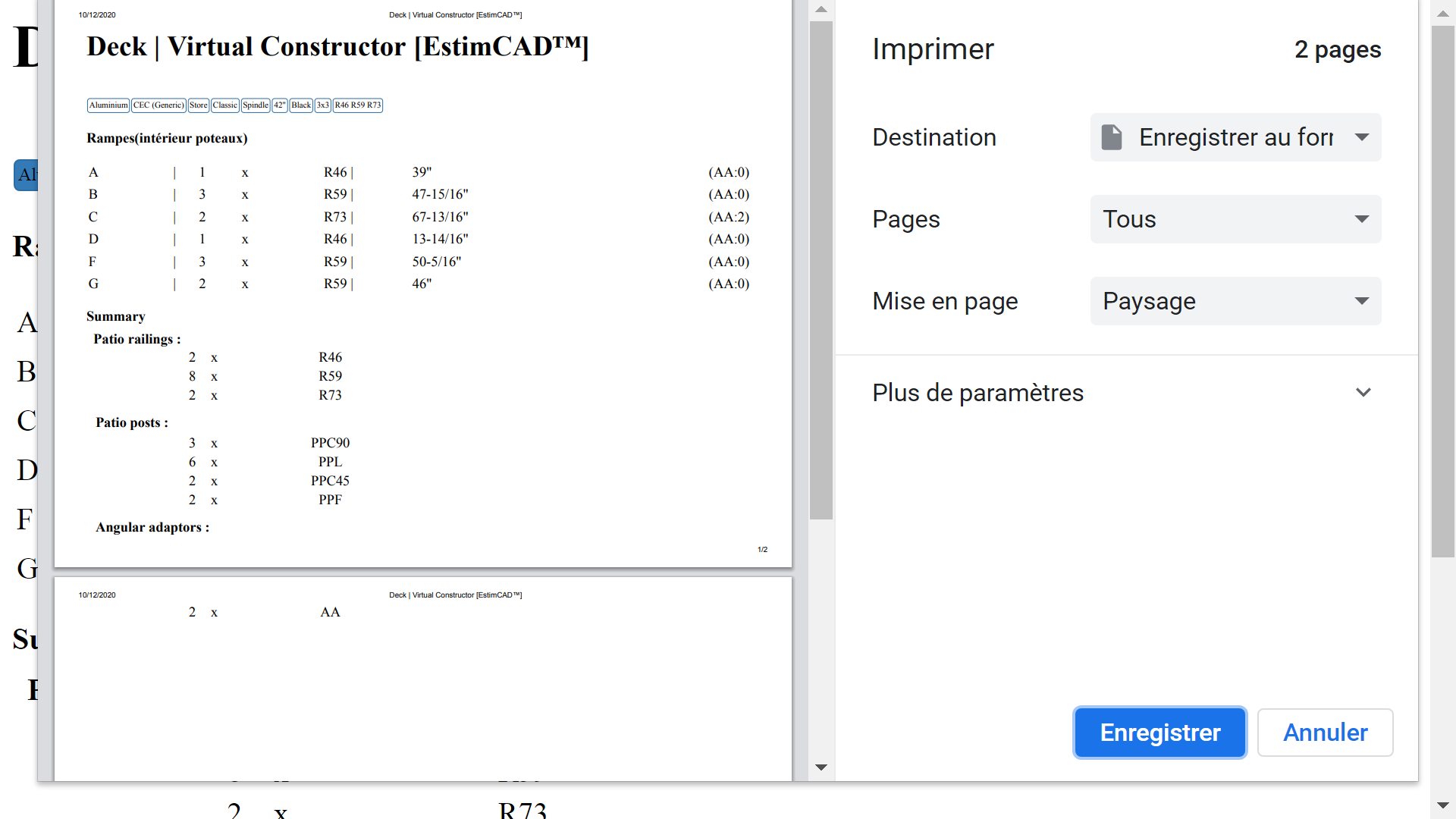
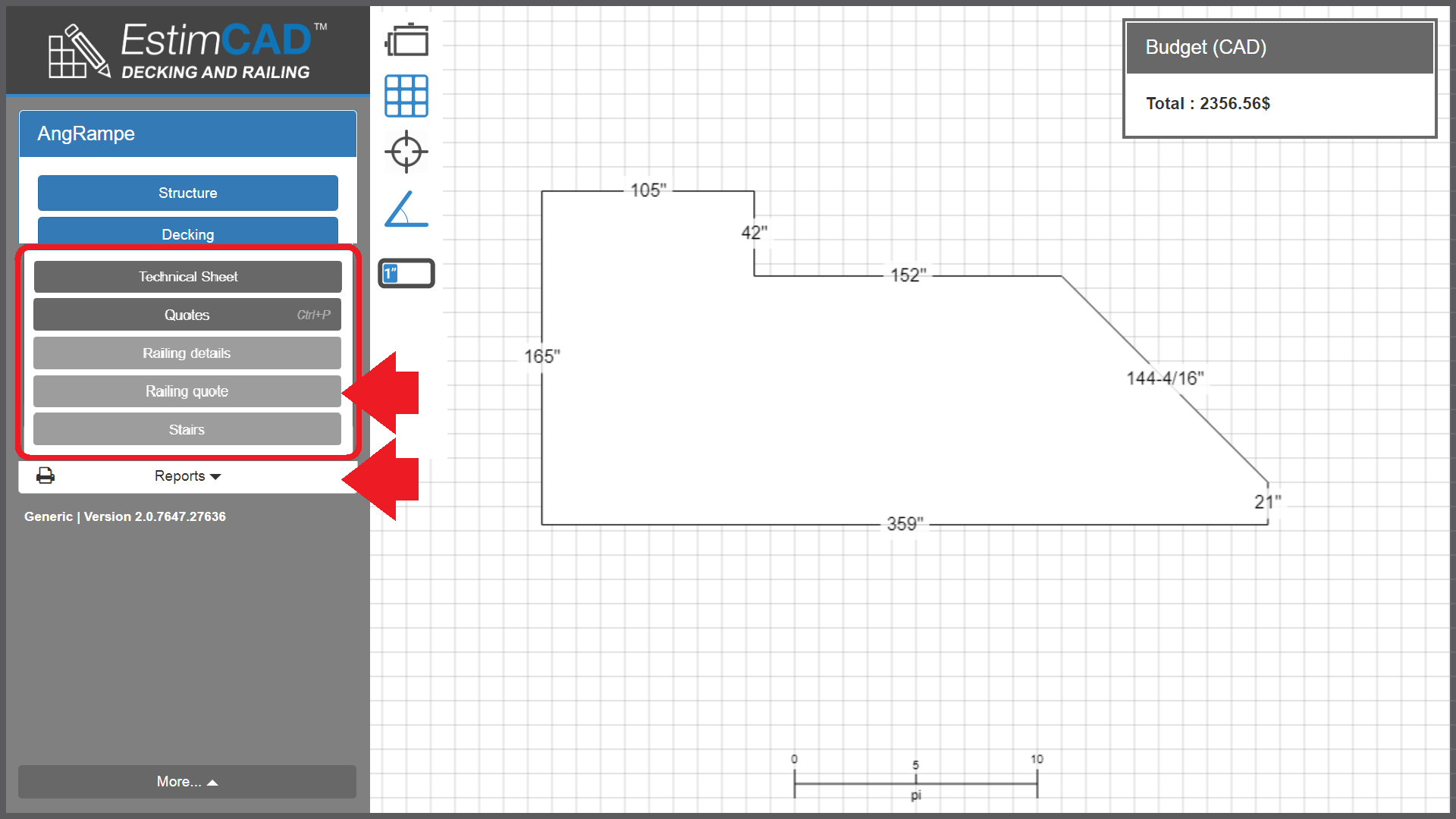
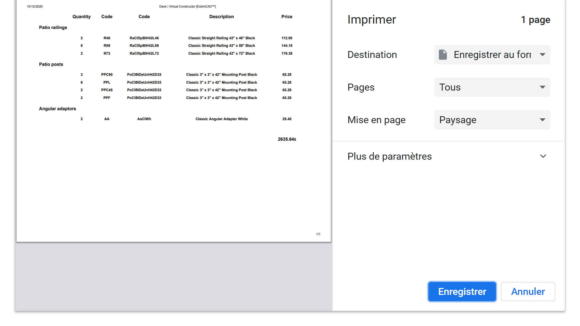
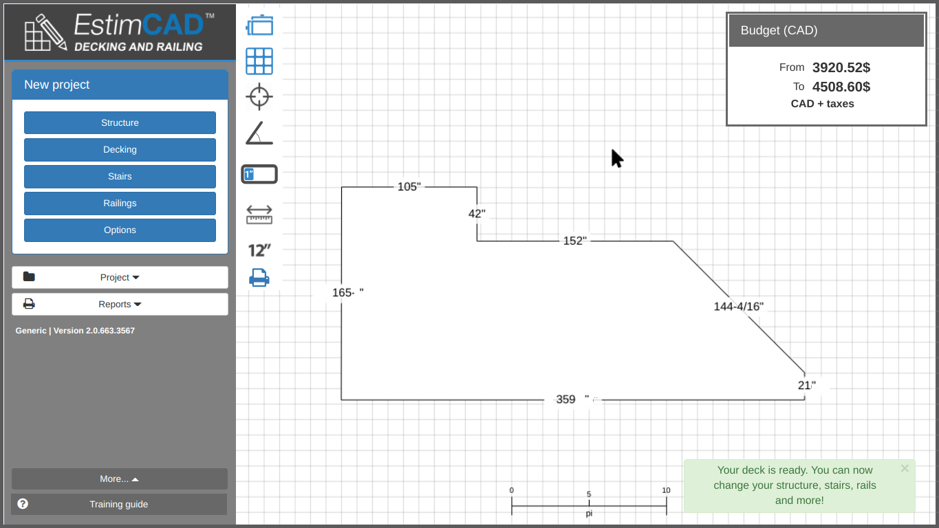
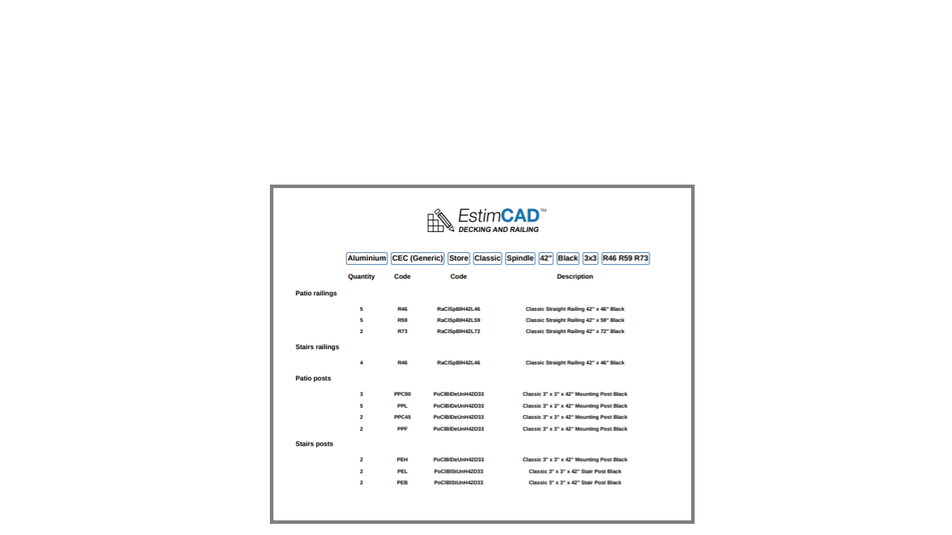
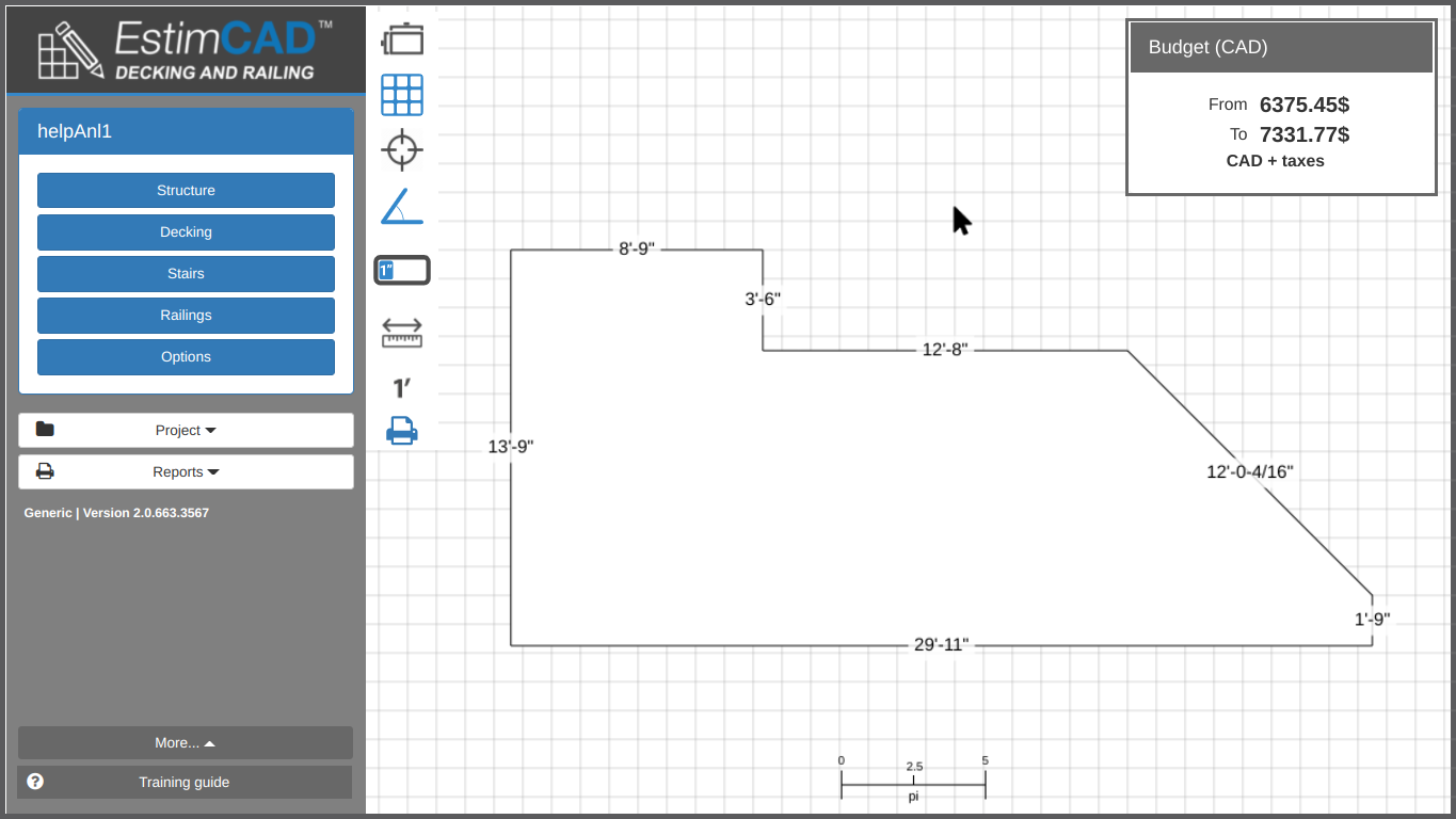
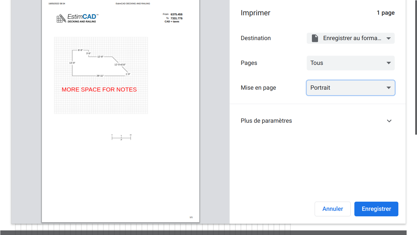
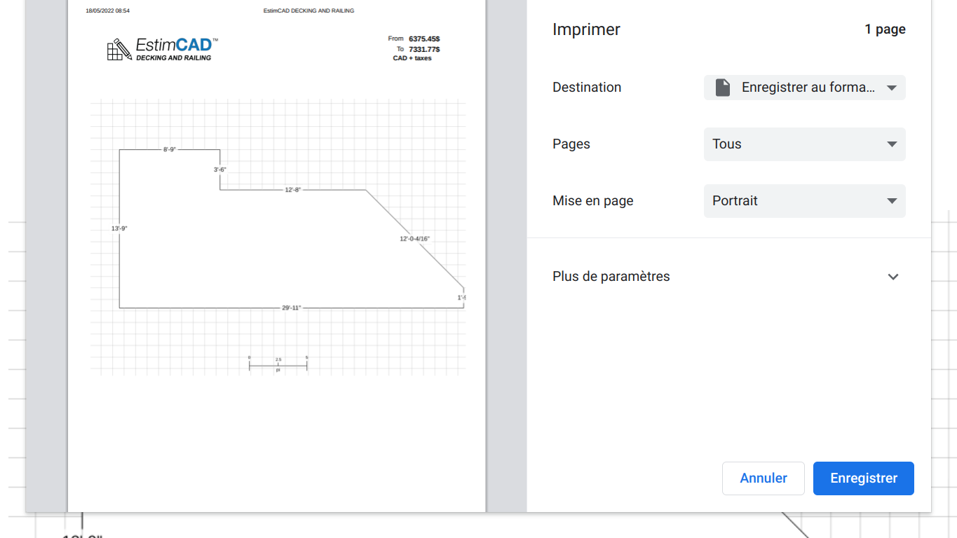
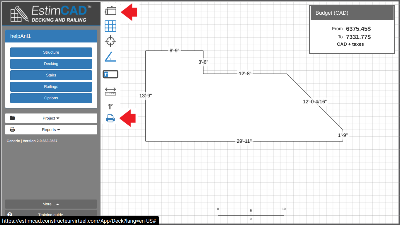
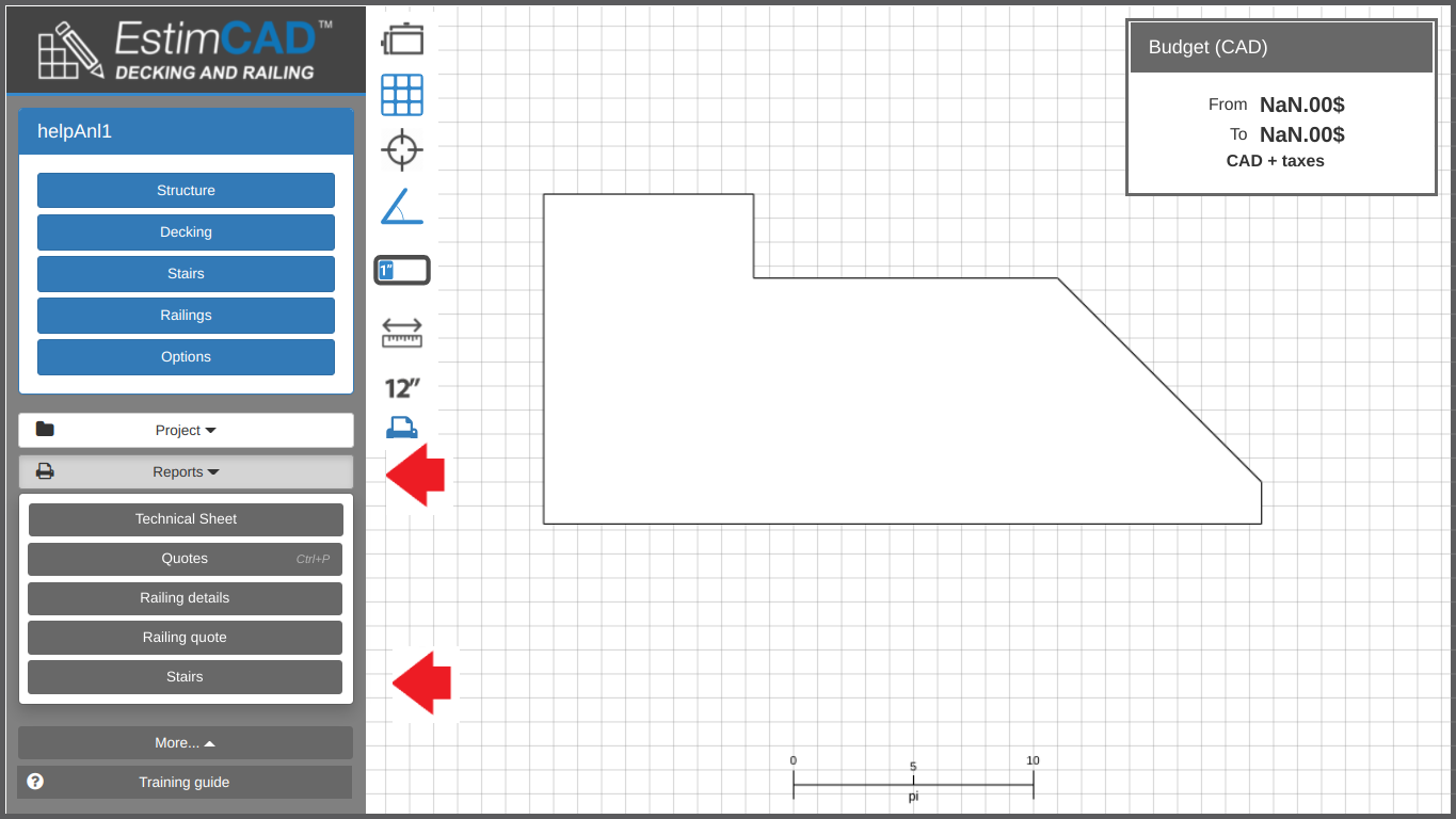
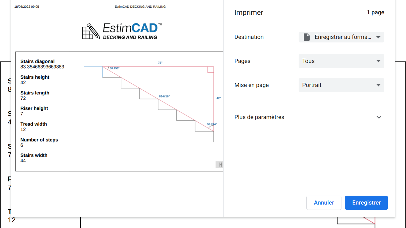
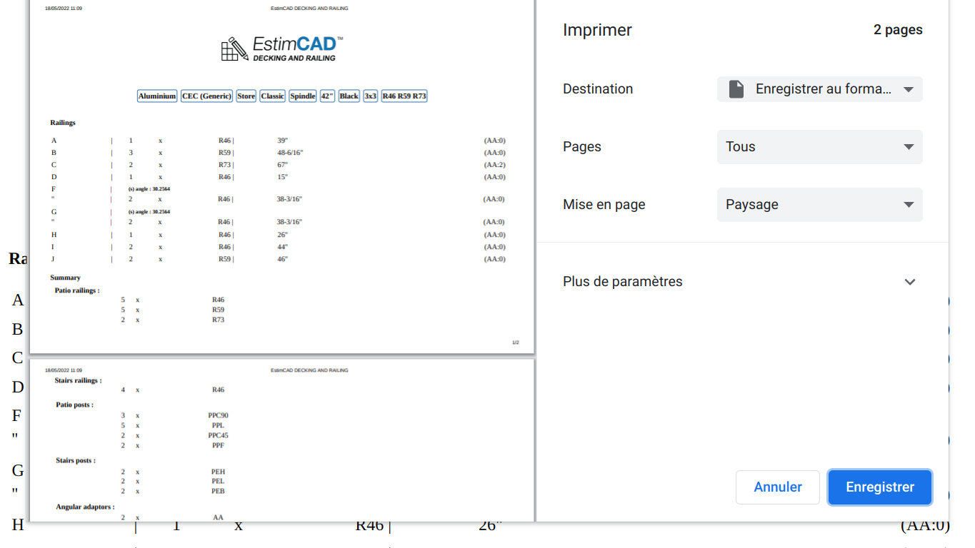
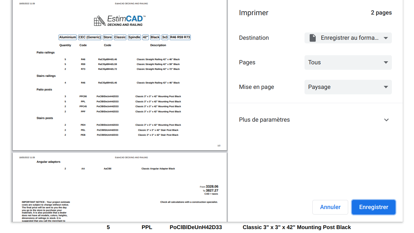
Understanding how to compile and deliver a well-ordered file to a client which would serve him as a kind of installation guide and benchmark because the application allows printing several formats of plans, reports, a detailed list of materials and a quote, as shown in the following slideshow.
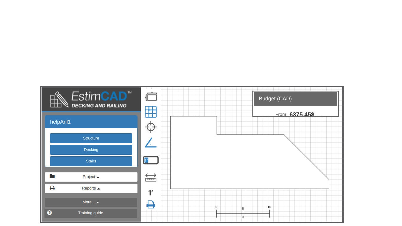
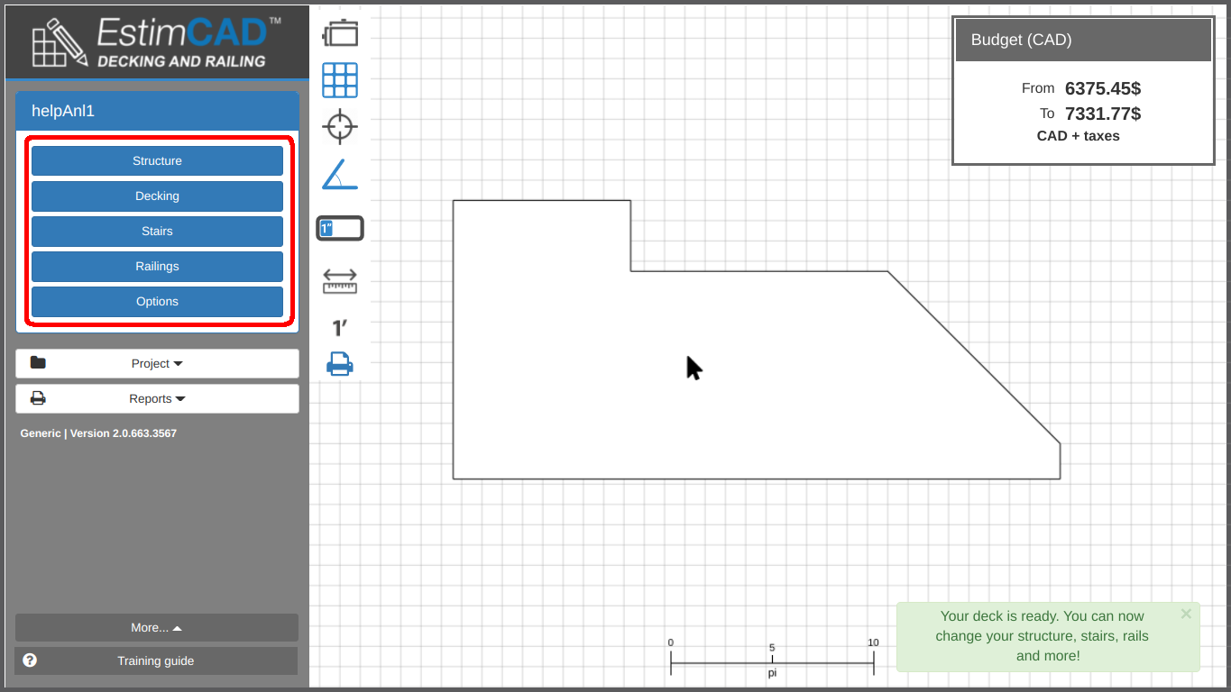
Understand the overview of the user interface as illustrated in the following slideshow.
Our online CAD distinguishes from others by its simple UI and its ease of use to estimate the components of structures, stairs and railings with a precision down to one sixteenth of an inch.
This section will detail some of the interface components used throughout the application.
ICONES
Throughout this guide you will encounter the following icons :
| Icon | Description |
|---|---|
| Highlights important concepts in the current section | |
| Tips and tricks | |
| Noteworthy information |
Search for a small question mark () near something you wonder about and hover your mouse over it to display a helpful message about what it does or how it is used.
For the best drawing and plan interaction experience, we recommend understanding the following icons. Most of these are always available on the left side of the viewport (the area for drawing and interacting with the plan).
| Icon | Description |
|---|---|
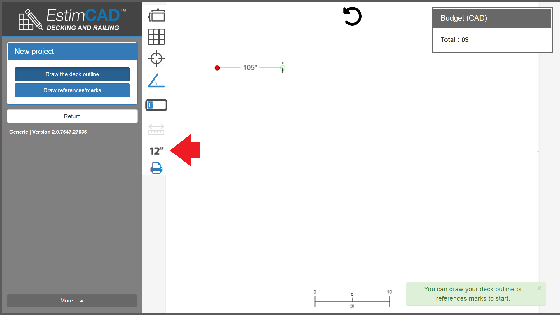
| Changes the precision of the grid and drawing. Precision of 12", 6" and 1" available | |
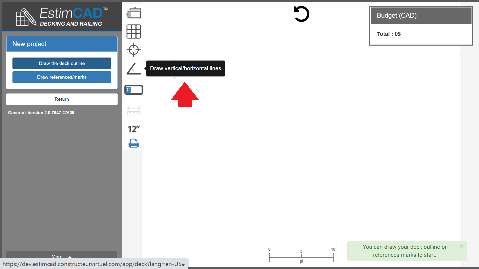
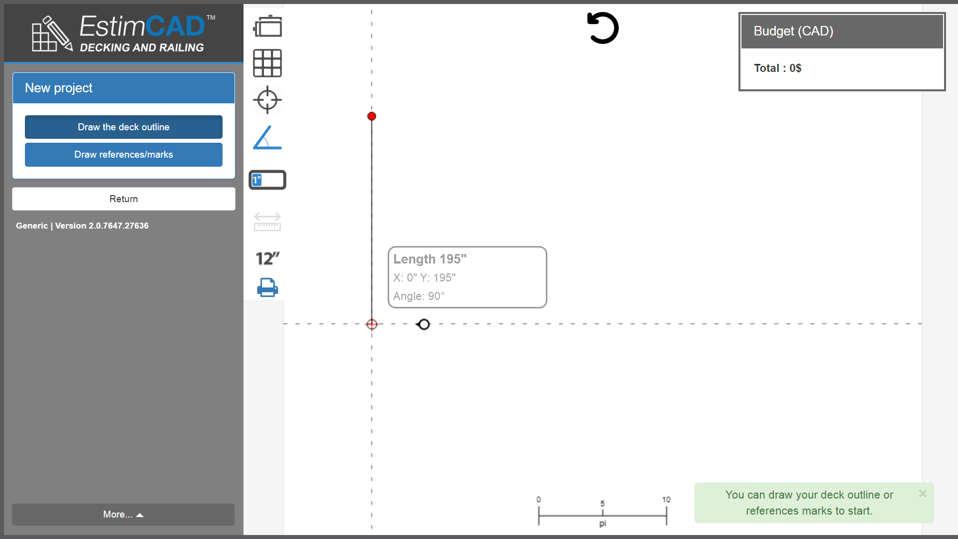
| Forces your lines to either be vertical or horizontal. If you have an angle to draw, disable it. | |
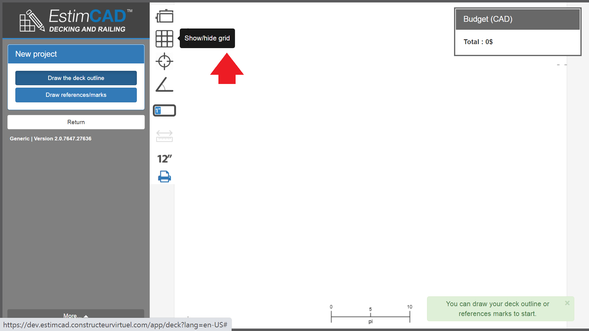
| Toggles the visibility of the background grid at the chosen precision. Do no hesitate to remove it, it is only a visual assist. | |
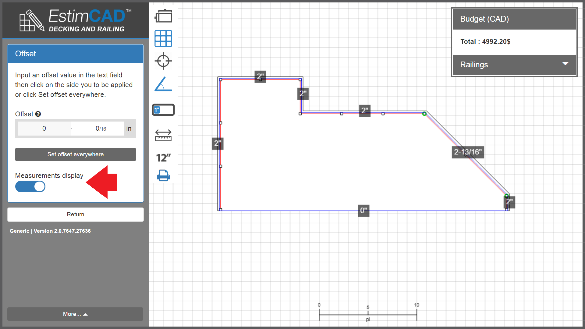
| Toggles the visibility of measurements around your deck outline. | |
| Appears while drawing. Allows to undo one point at a time. In the current version of the software, you cannot edit the outline once it is traced. Therefore, your initial tracing is critical. |
Here is a little help with how the construction lines work in EstimCAD.
The viewport is the big area for drawing and interacting with the plan.
You can move and zoom around the viewport to draw precise measurements or to inspect a plan.
Hold the right mouse button and drag your mouse around the viewport to move around.
Scroll the mouse wheel while the cursor is in the viewport to zoom in and out toward or from the position of the pointer.
Right mouse button to move, mouse wheel to zoom
You will see that the grid size changes depending on the zoom level. It is trying to fit an appropriate amount of precision in the screen. Zoom and de-zoom to see the effect.
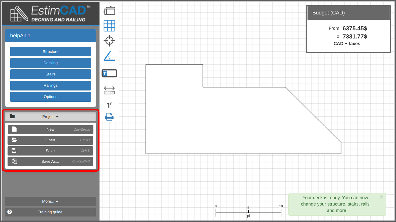
Save your projects with the save button in the project menu or by pressing CTRL+S
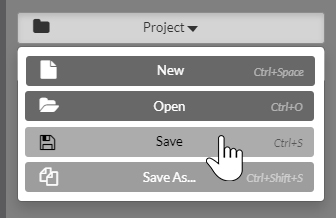
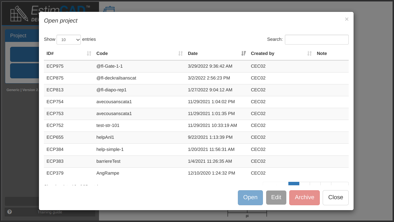
You can open and save many versions of a projects. Name them with unique and descriptive names that will remind you of what they are.
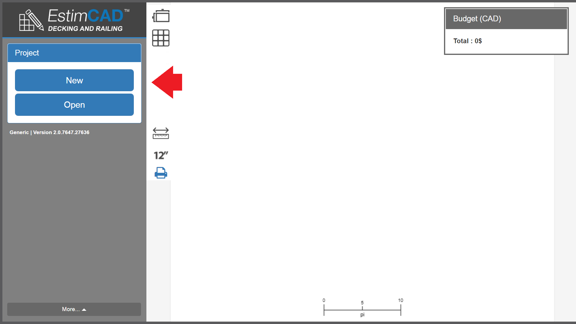
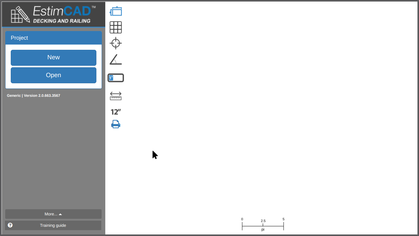
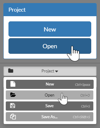
You can open projects using the “Open” button at the opening of the application or in the project menu.
Similarly, create new projects by clicking the "new" button or by pressing CTRL+SPACEBAR.
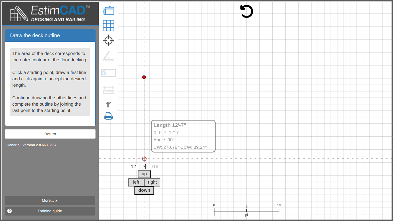
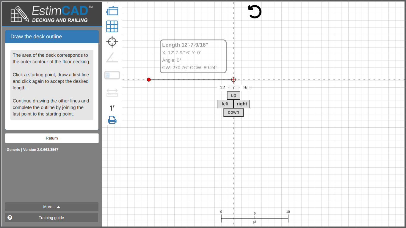
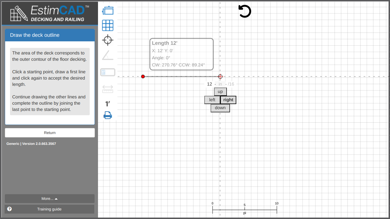
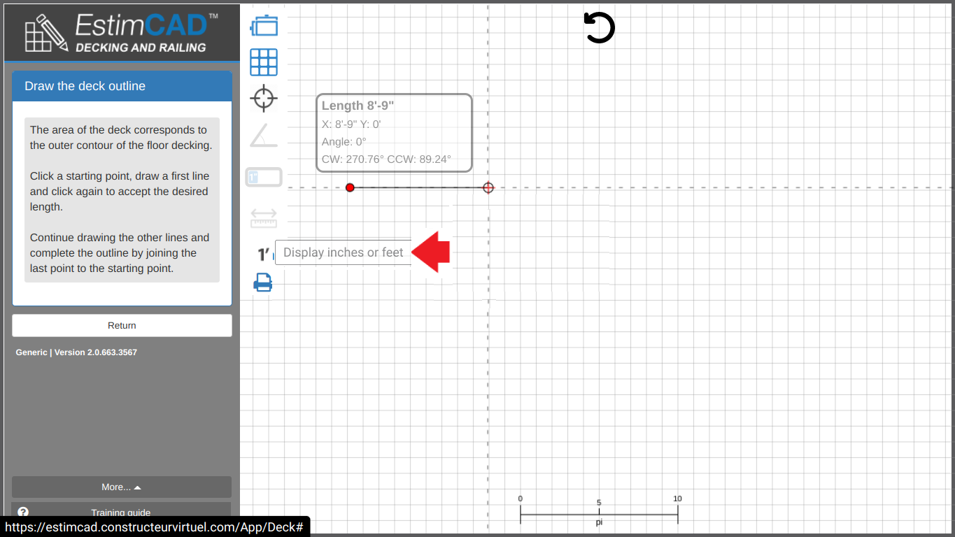
Whenever you need to enter lengths in the application there will be an input specially designed for that purpose.
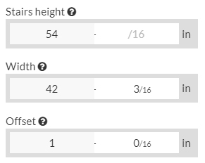
For imperial inputs, press the hyphen button on your numpad to go to the next input slot.
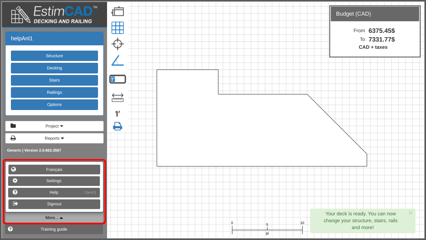
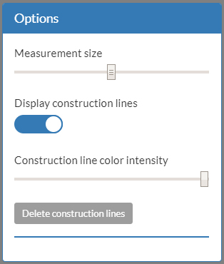
Once you are done tracing your plan, you have access to the “Settings” menu in the choices on the left. In this menu you will find some display settings allowing you to customize how the plan and the application is displayed.
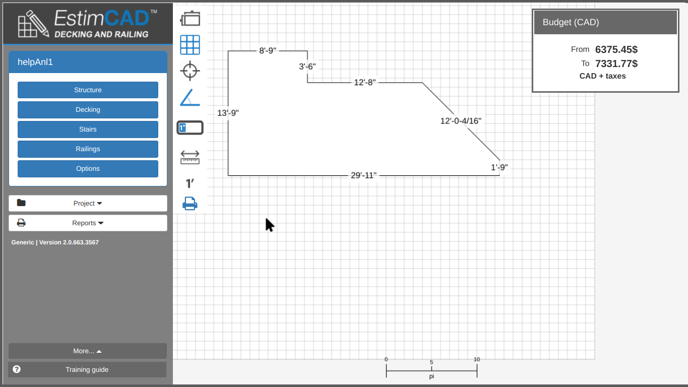
Notably, you can change the size of the measurements on the plan, allowing you to print big plans with big measurements and to zoom-in on small details and still understand what the measurements are.
Options relating to construction lines are also in this menu.
Here you can find a list of features and tips to illustrate how to use the application and how to handle some special cases.
Tracing a plan is core to the use of EstimCAD. Once an outline is closed, a plan is created and calculated instantly.
First you need to do those TRAININGS on
Identify measures on existing deck
Draw a plan easily (mouse)
If you think you are ready, you could also do this TRAINING on
Draw a plan like a pro (keyboard)
Then, continue with all the different explanations below.
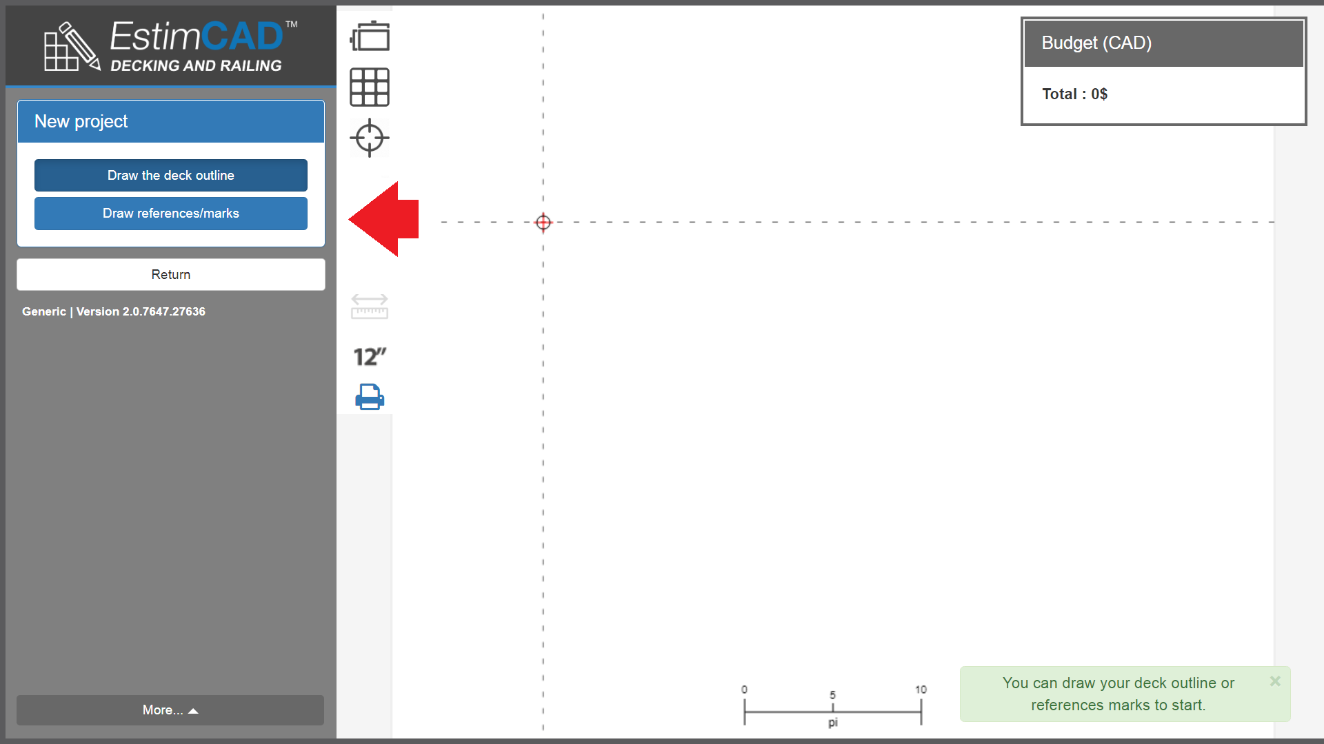
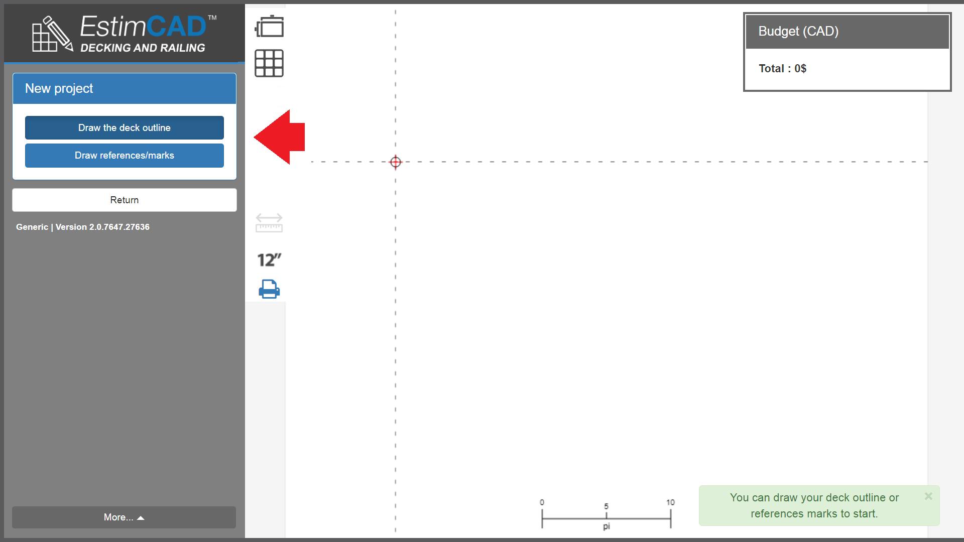
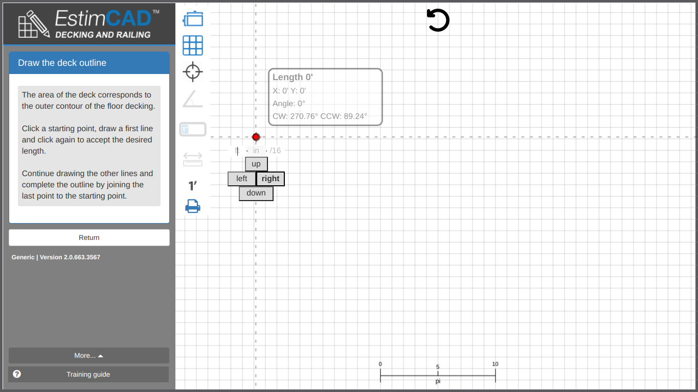
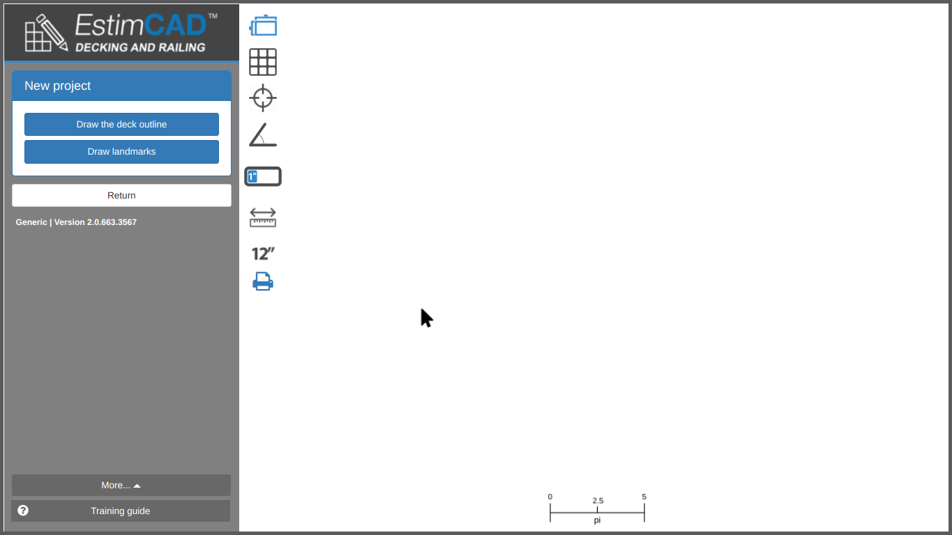
Start by creating a new project in drawing mode. Refer to the Save, load and create projects section to learn how to start a new project. The drawing mode is then activated automatically.
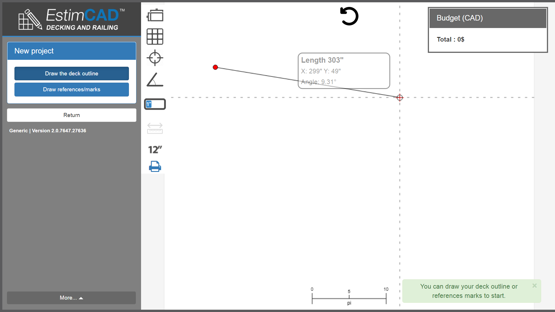
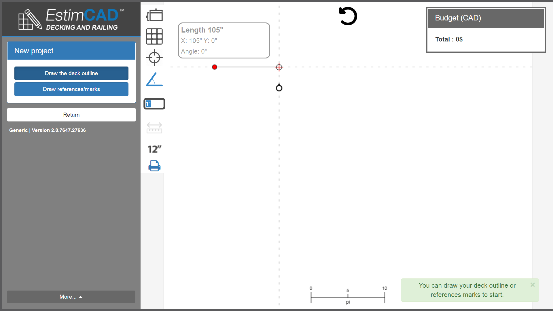
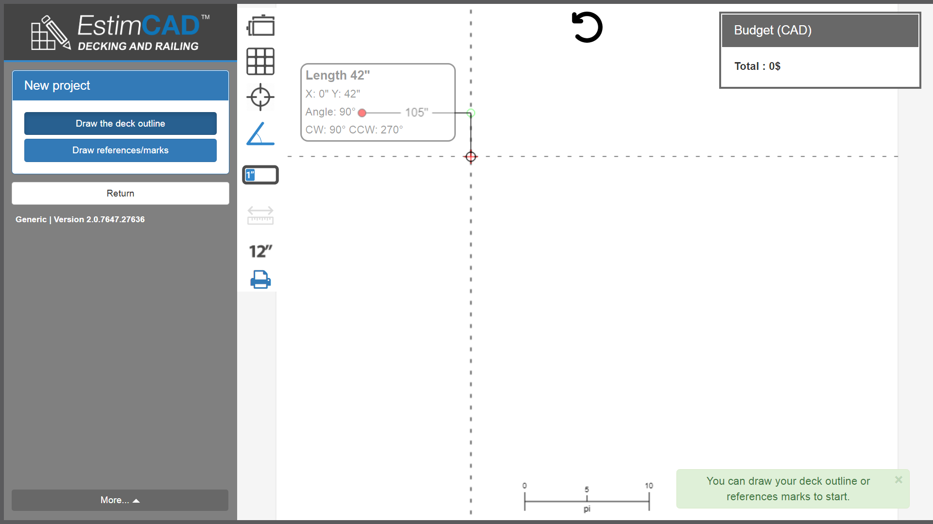
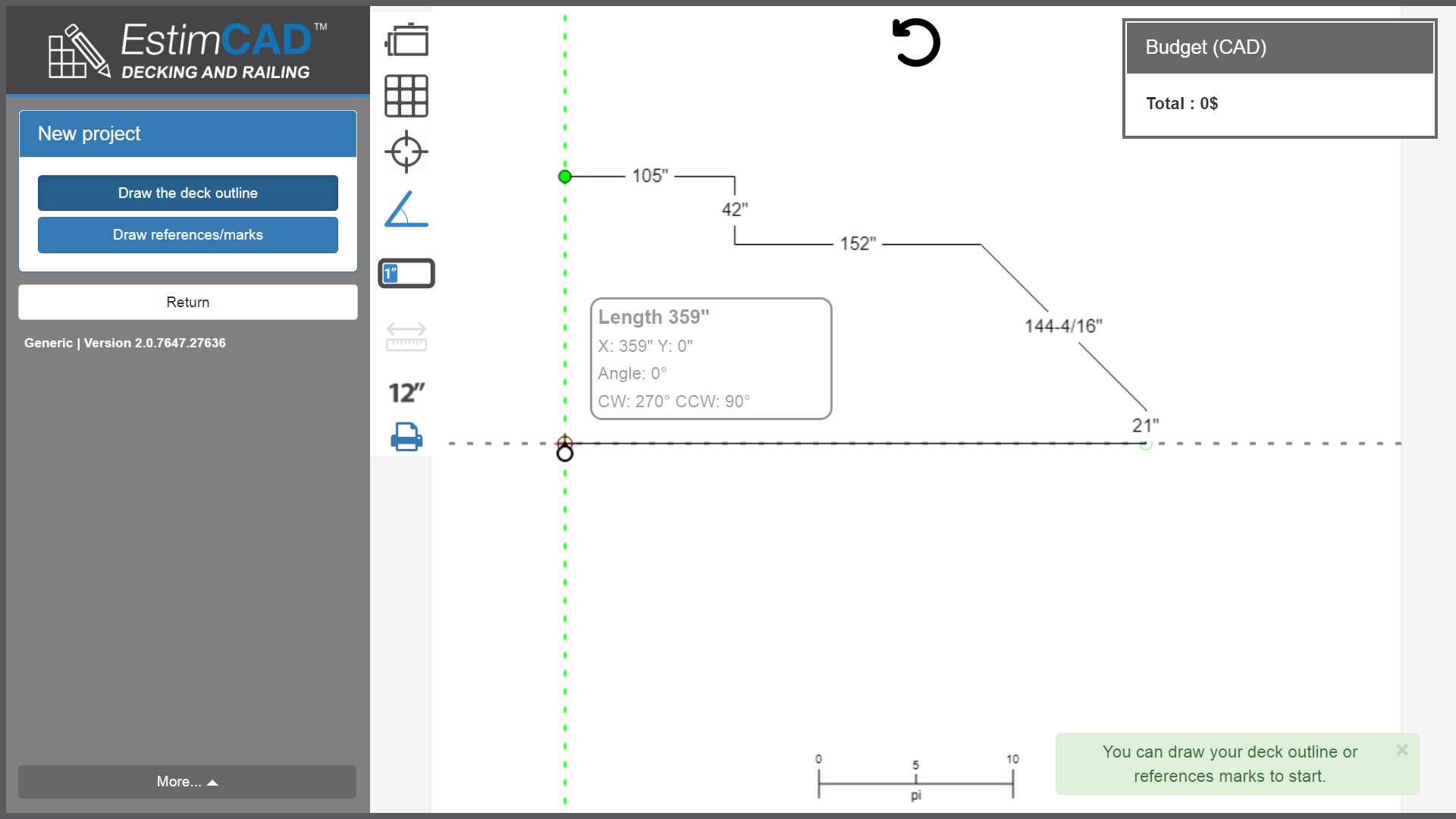
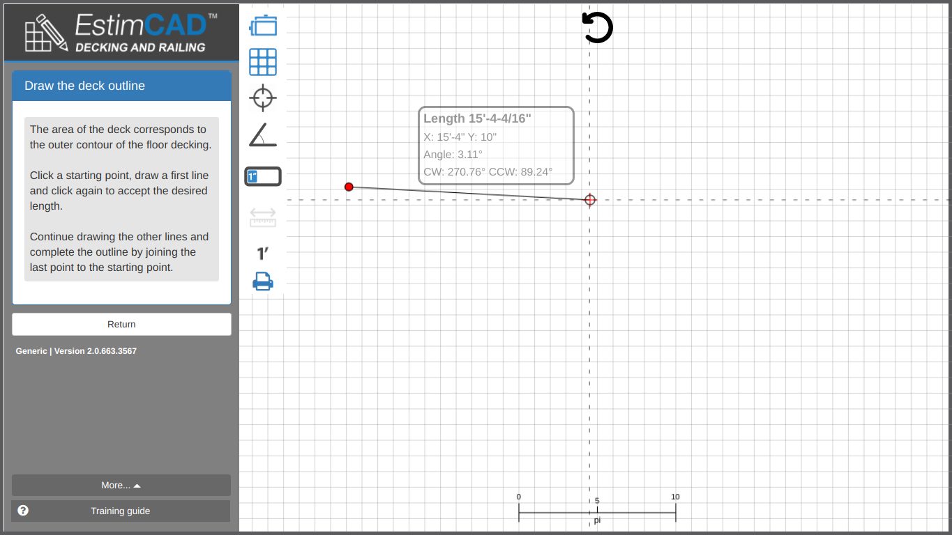
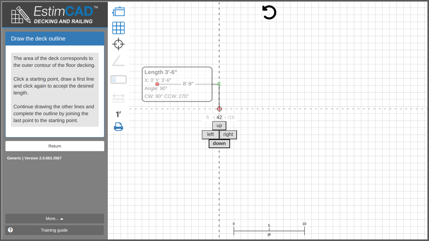
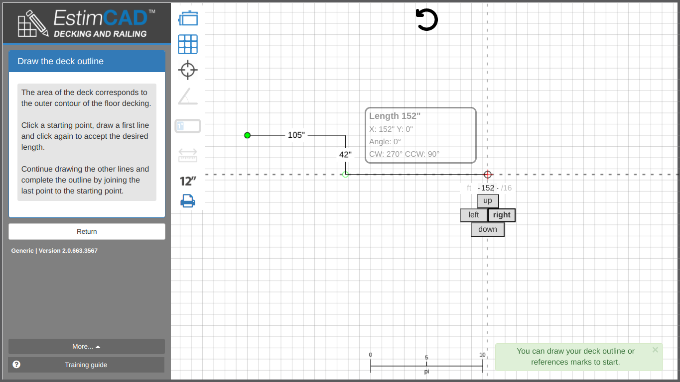
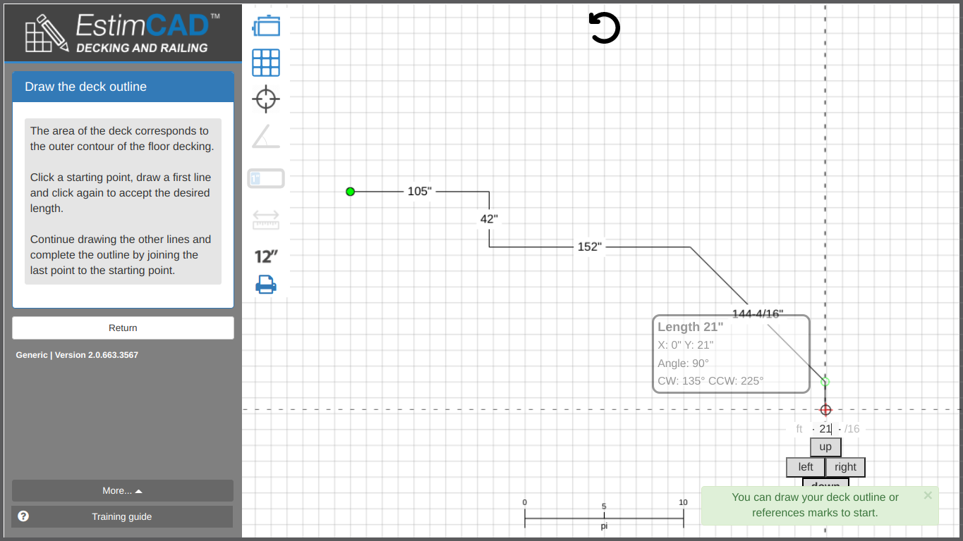
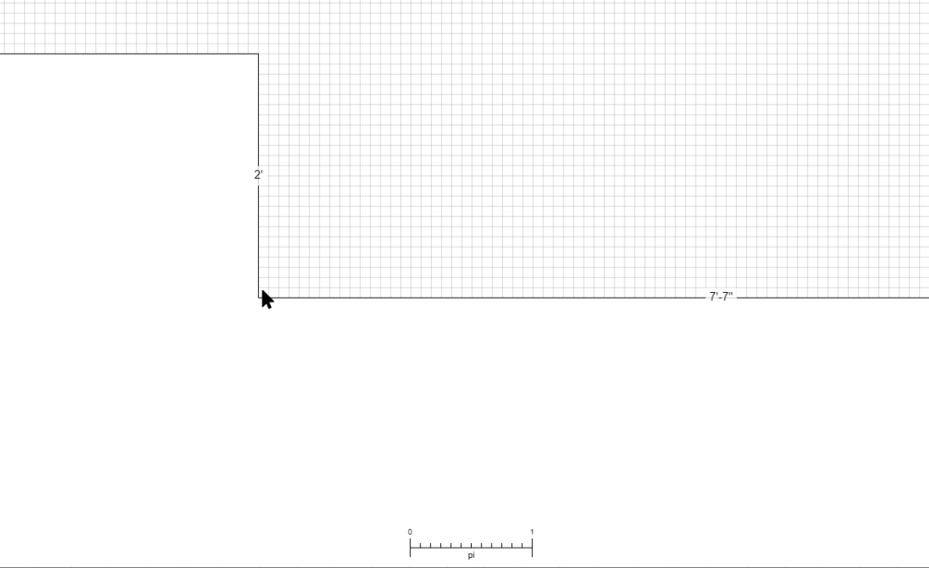
Once in drawing mode, click on the plan to place a point. Move your mouse around the viewport to see the line your are currently drawing.
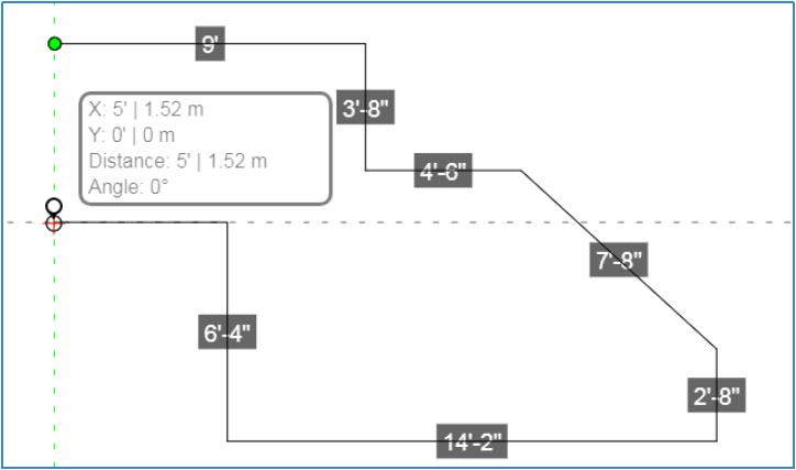
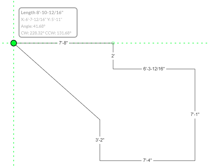
Place your first point leaving enough space to trace in the desired direction. Here we decided to place the first point on the left side of the plan so there would be enough space on the right side to draw the deck.
In the the following image, the green point is the start point. We traced a first 9’ (nine feet) horizontal line followed by a 3’-8“ vertical one. The third line at 9’-4” is currently being traced.
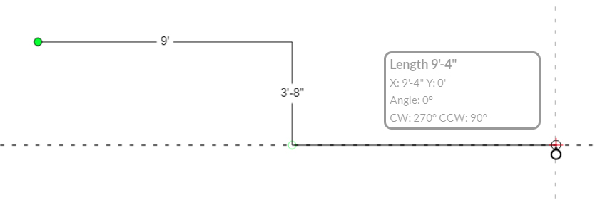
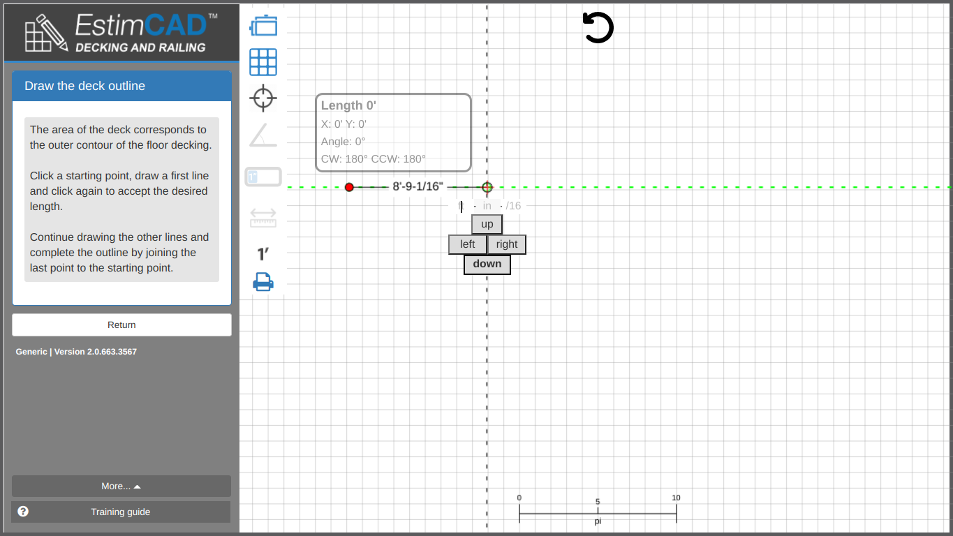
The rounded rectangle displays information relating to the segment you are currently drawing.
The X Axis is horizontal and the Y axis is vertical.
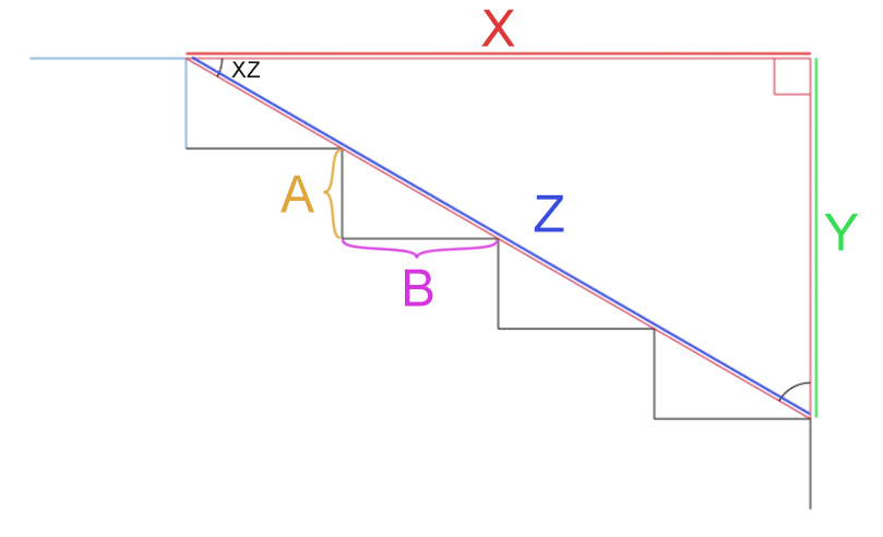
The following image illustrates the mathematical formulas used to calculate the lengths displayed. No need to understand them, but it may help some to understand what the numbers actually are.
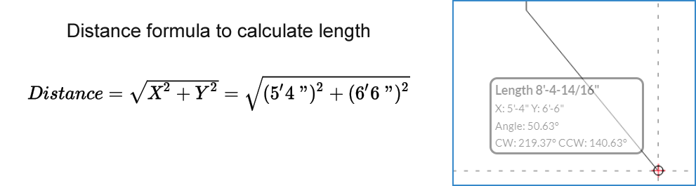 X : Horizontal
distance between current and last point.
X : Horizontal
distance between current and last point.
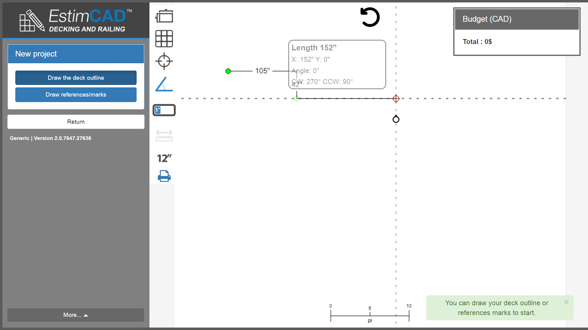
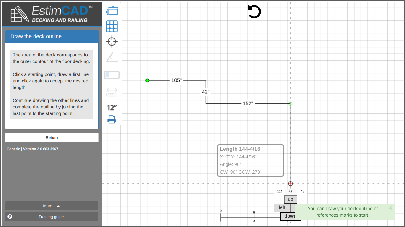
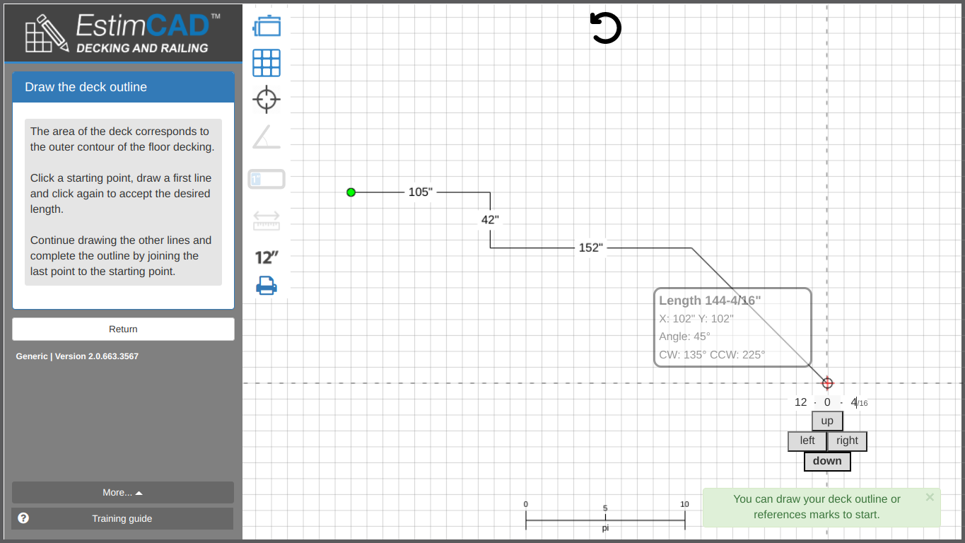
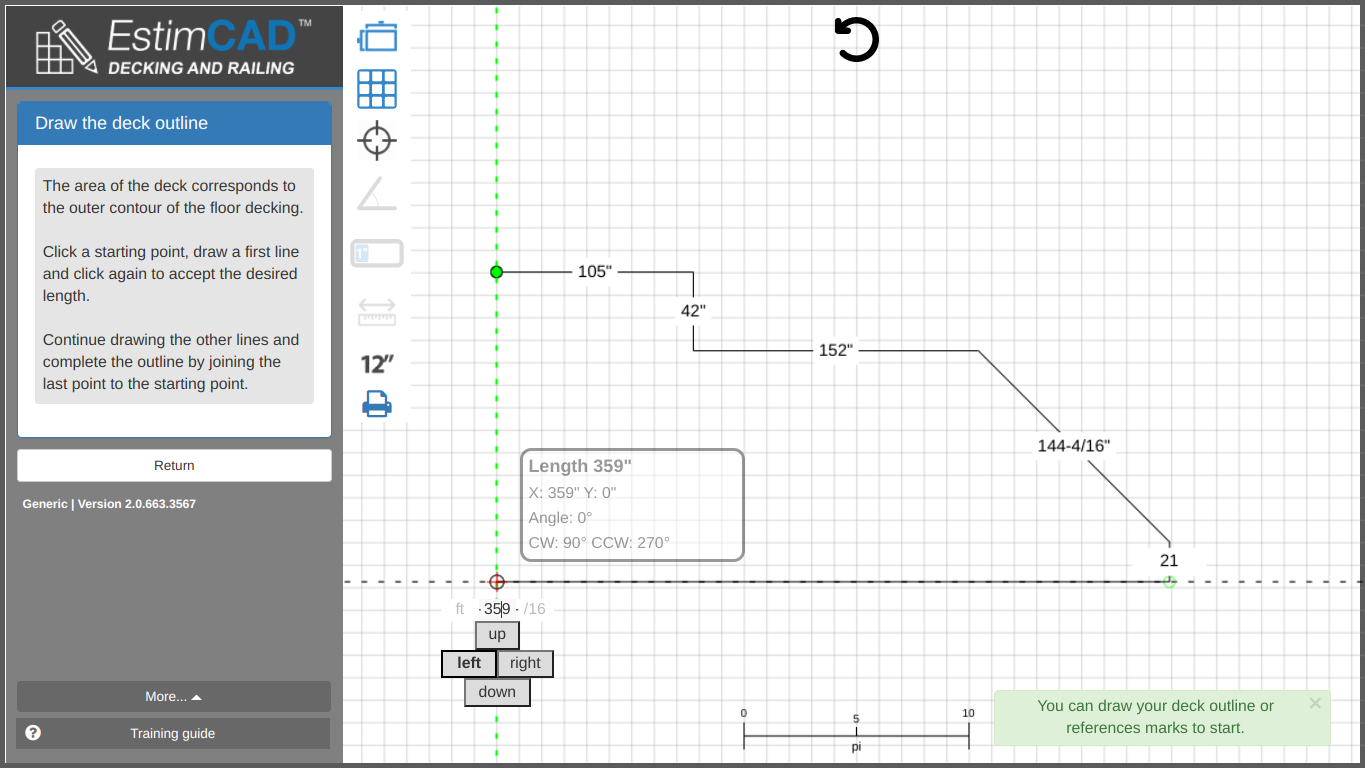
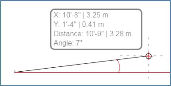
The angle that is displayed is always related to the horizontal axis (X) shown in red in image below.
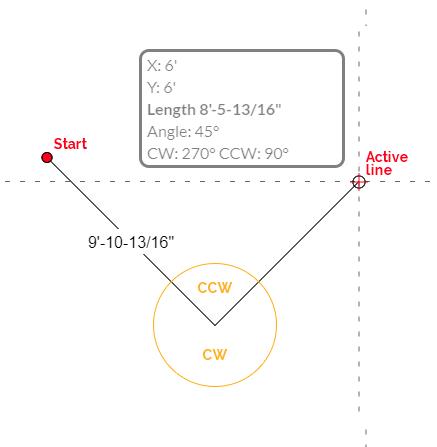
The CW and CCW angles are the Clockwise and Counter- Clockwise angles between the active line and the previous one. The sum of these 2 angles is always 360 degrees.
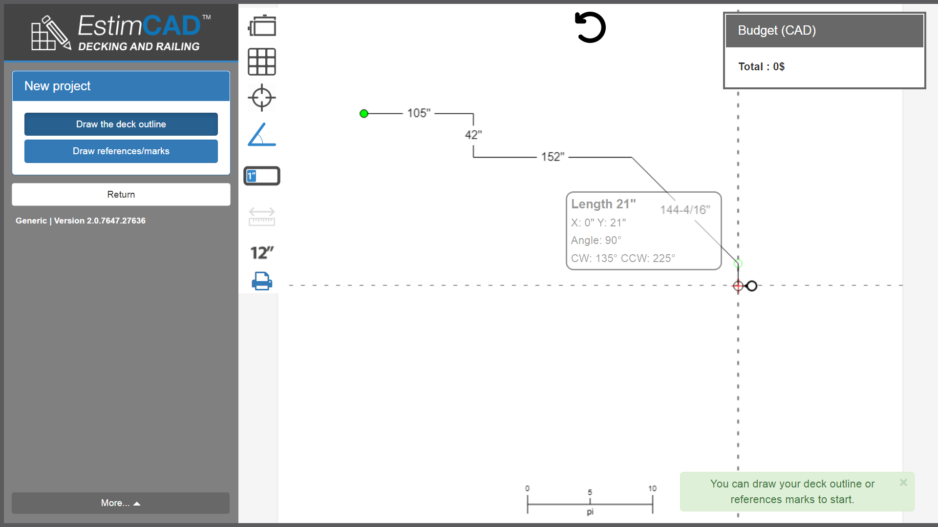
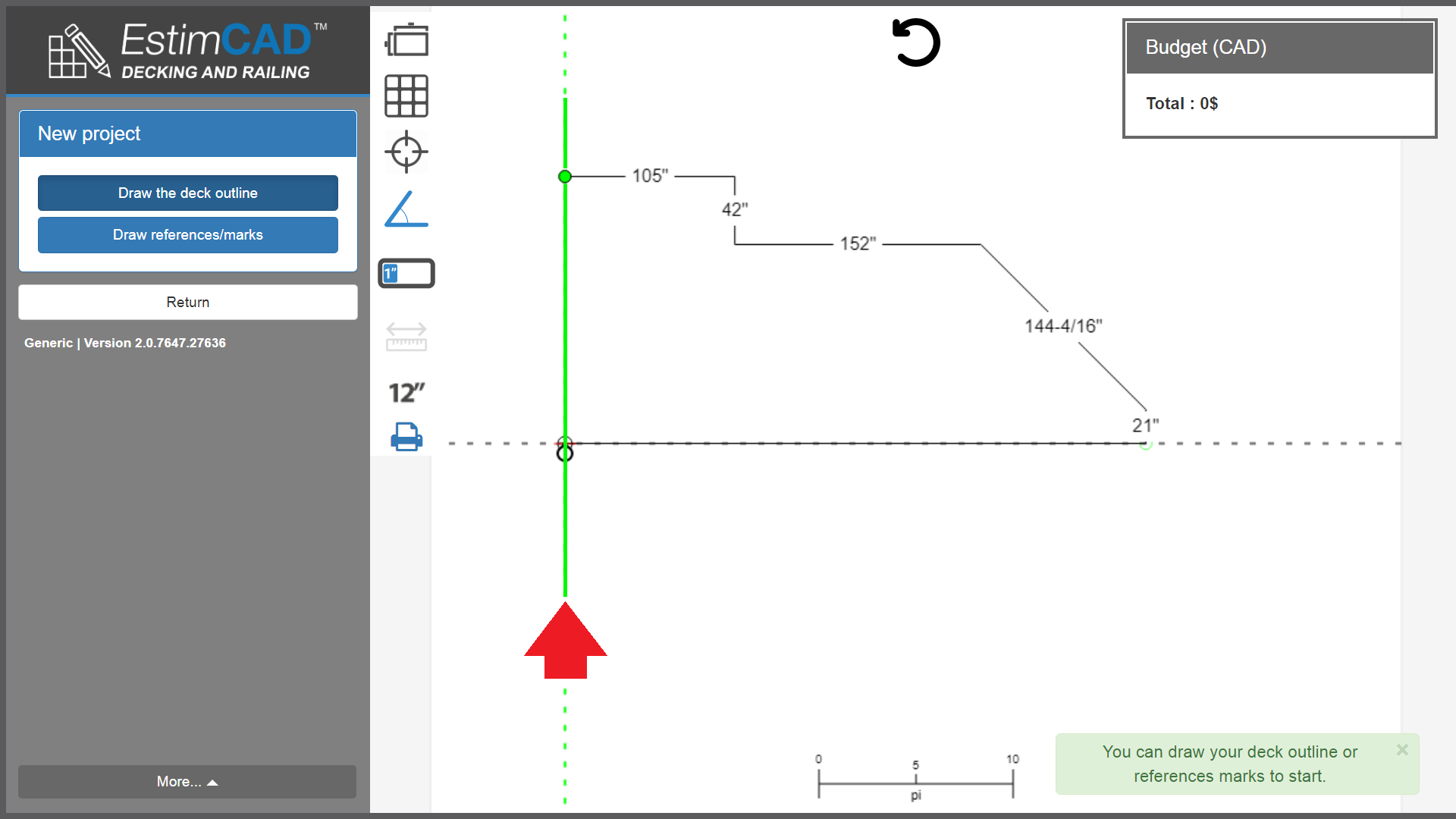
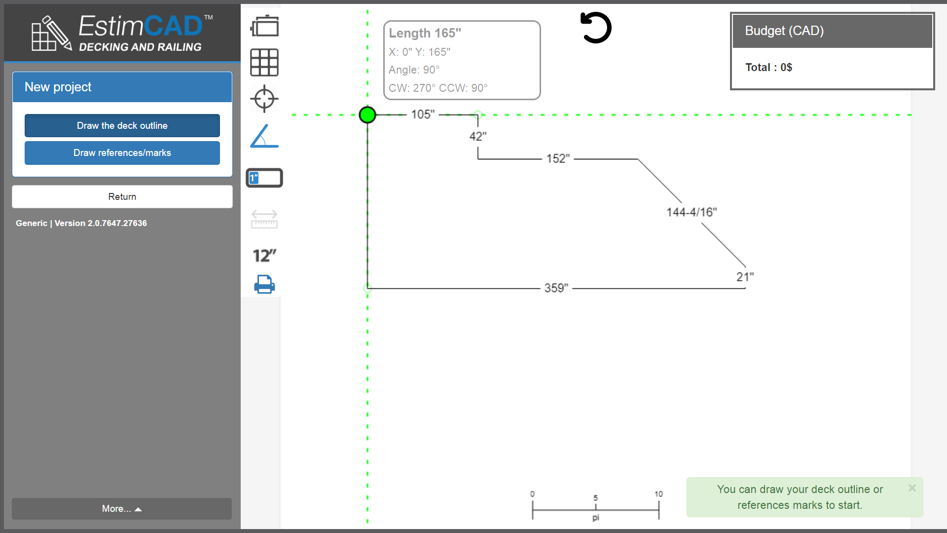
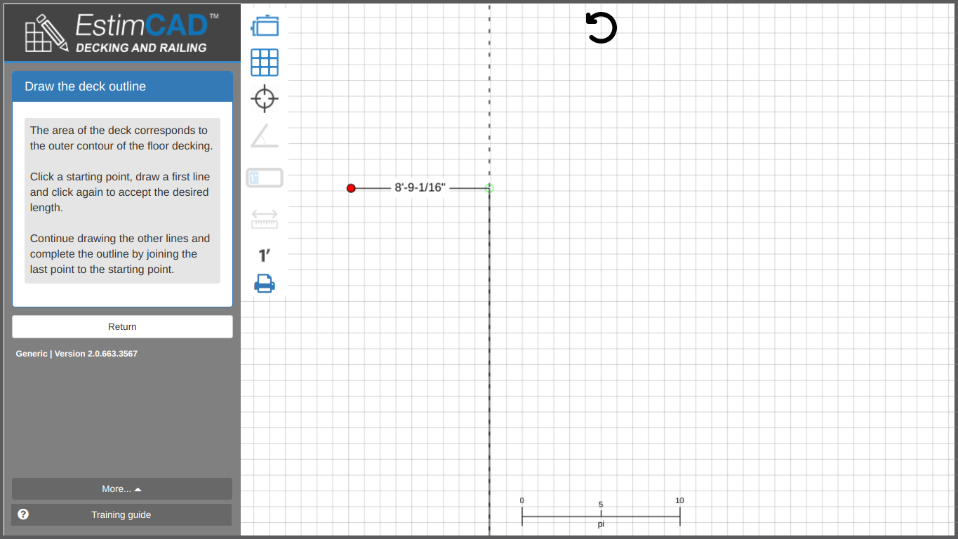
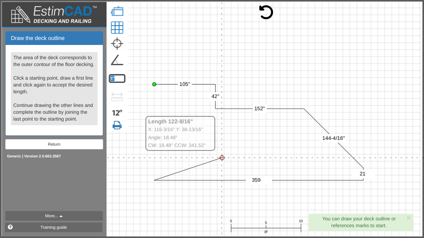
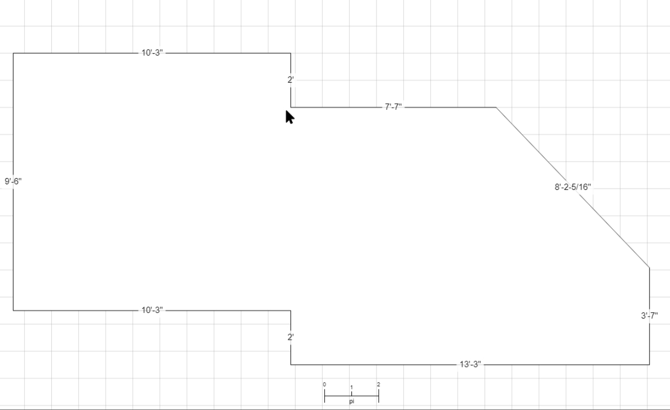
To finish the outline simply close the polygon by tracing to its starting point (green).
In the next image we can see the vertical guide turning green meaning we are aligned with our starting point.
This polygon only needs to be closed on the green start point to be calculated automatically and instantly.
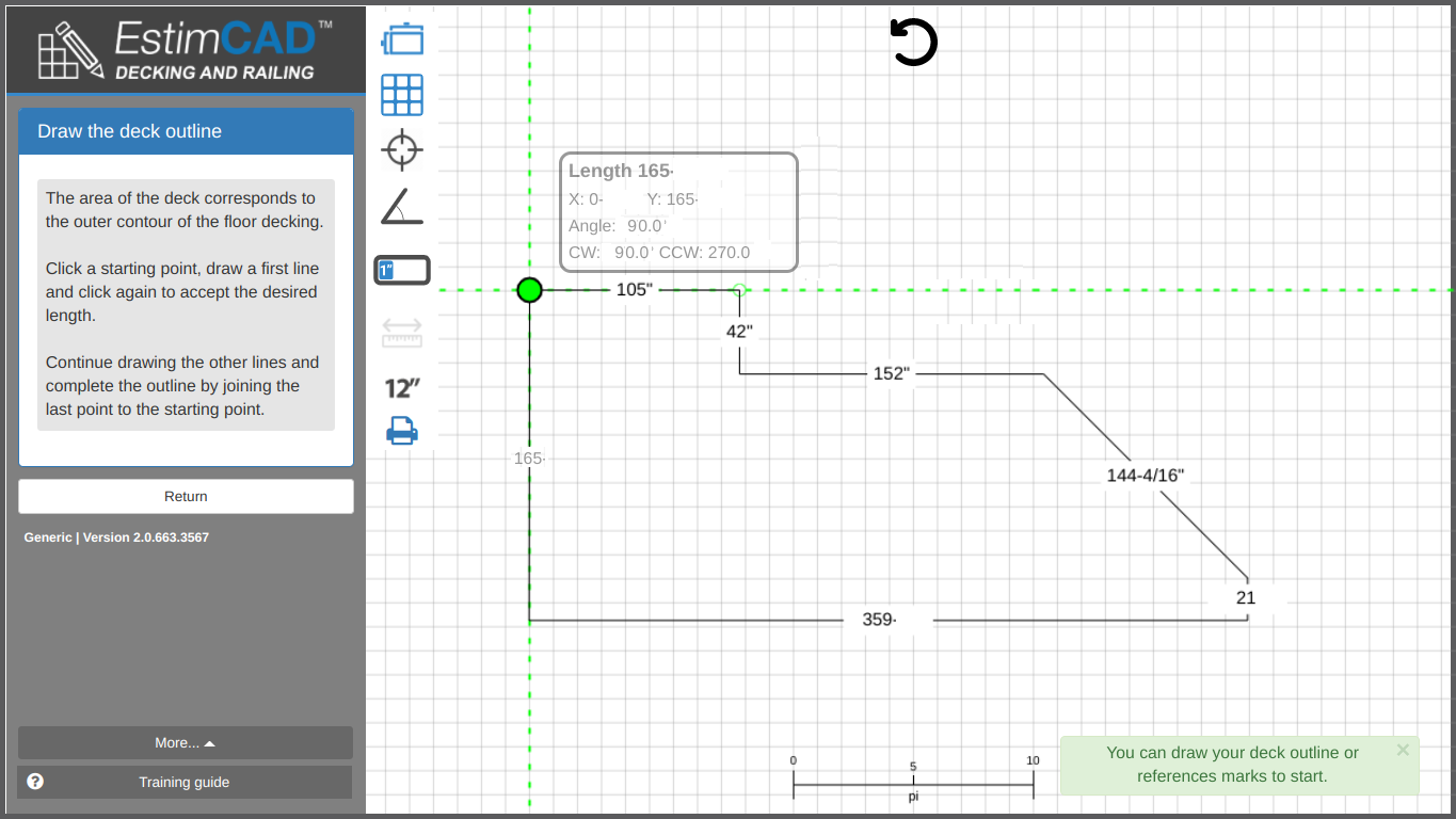
We recommend that you activate the following 2 functions if you want to trace with 1/16” precision easily.
| Drawing precision: Set to the smallest possible measurement | |
| Forces lines to either be vertical or horizontal. |
Let’s say you want to trace 10’ - 9 – 5/16" therefore trace until 10’-9" ...
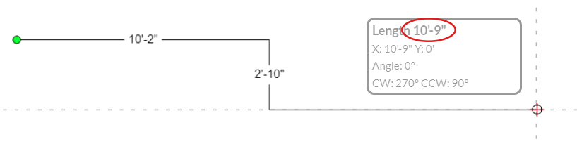
... then press CTRL and hold it. This should display the precision scale (image below). Move your pointer up and down to choose the desired length to add to the segment. Click to accept. You can then release CTRL.
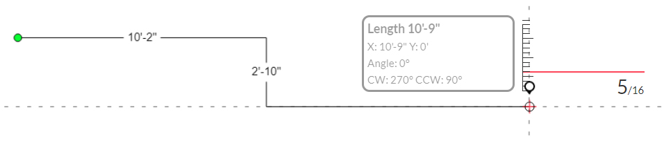
Press CTRL to display the precise measurement picker.
Holding the CTRL button enables you to release it if your original measurement is not right or moved. In the event you would have preferred to trace a 10’-8-5/16” measurement instead, you can just release CTRL, move the pointer and press it again.
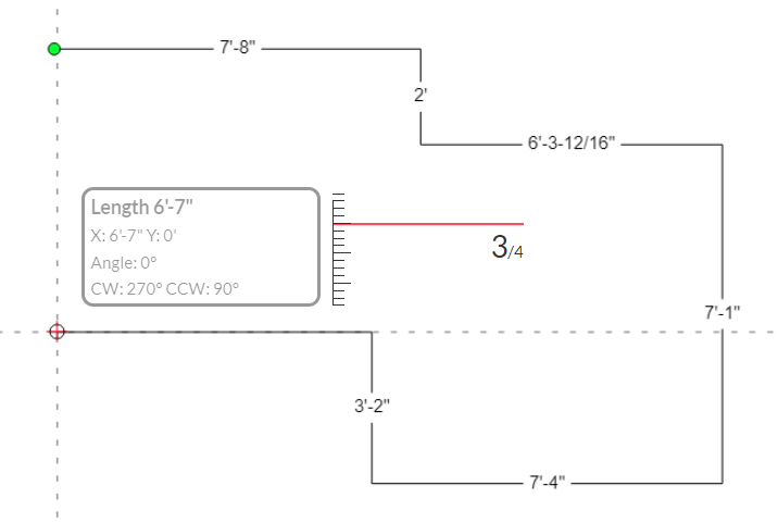
To avoid mentally calculating what is left from the X/16” measurements (image below)...
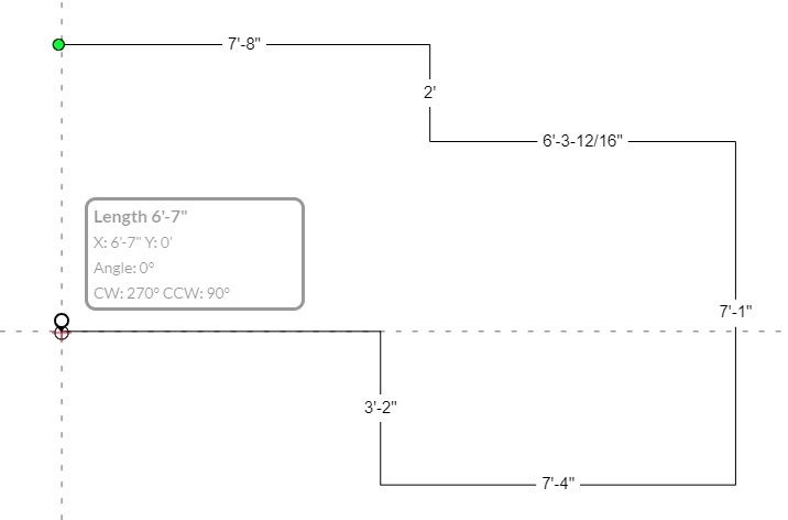
… hover the start point with your pointer and it will be calculated automatically.
Then just add this measurement (12/16”) to the line you want to trace. (12/16” = ¾”)
First you need to do this TRAINING on
Create and place stairs
Then, continue with all the different explanations below.
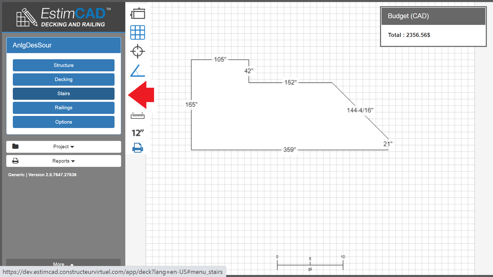
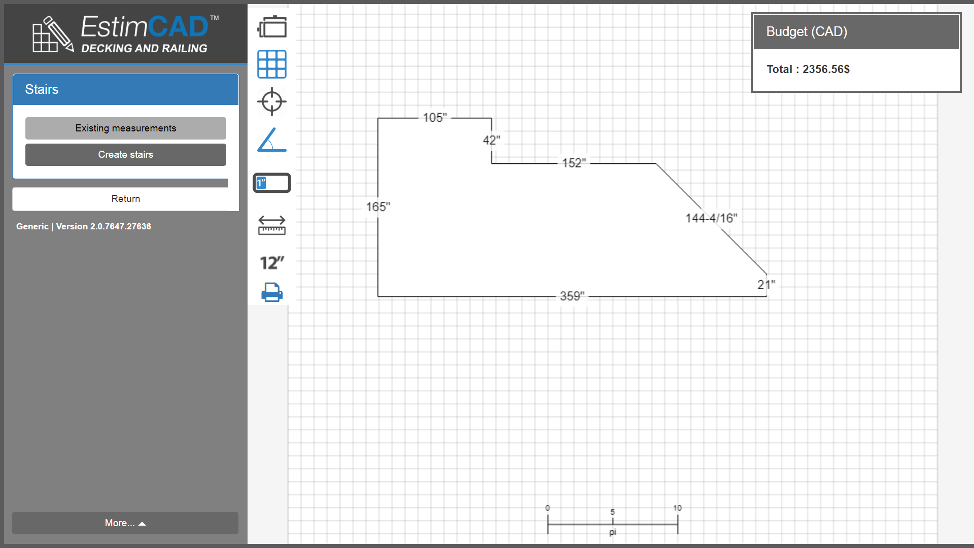
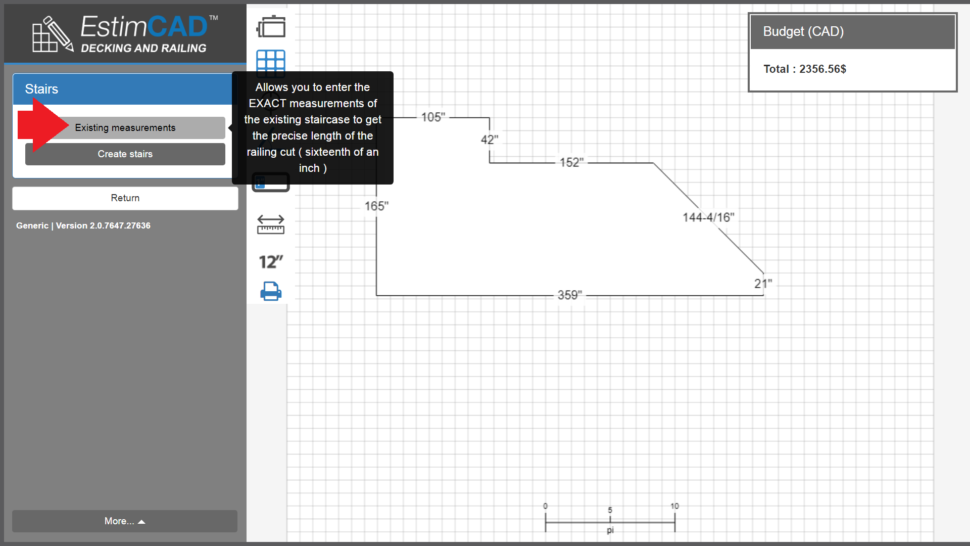
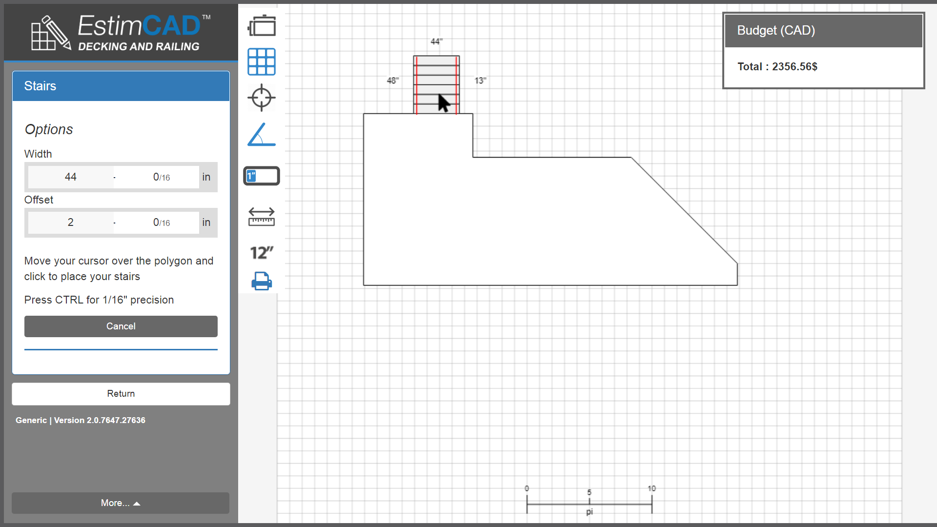
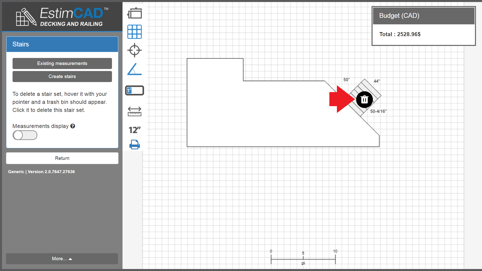
Click on the “Stairs” menu and you will find a button labeled “Add stairs”.
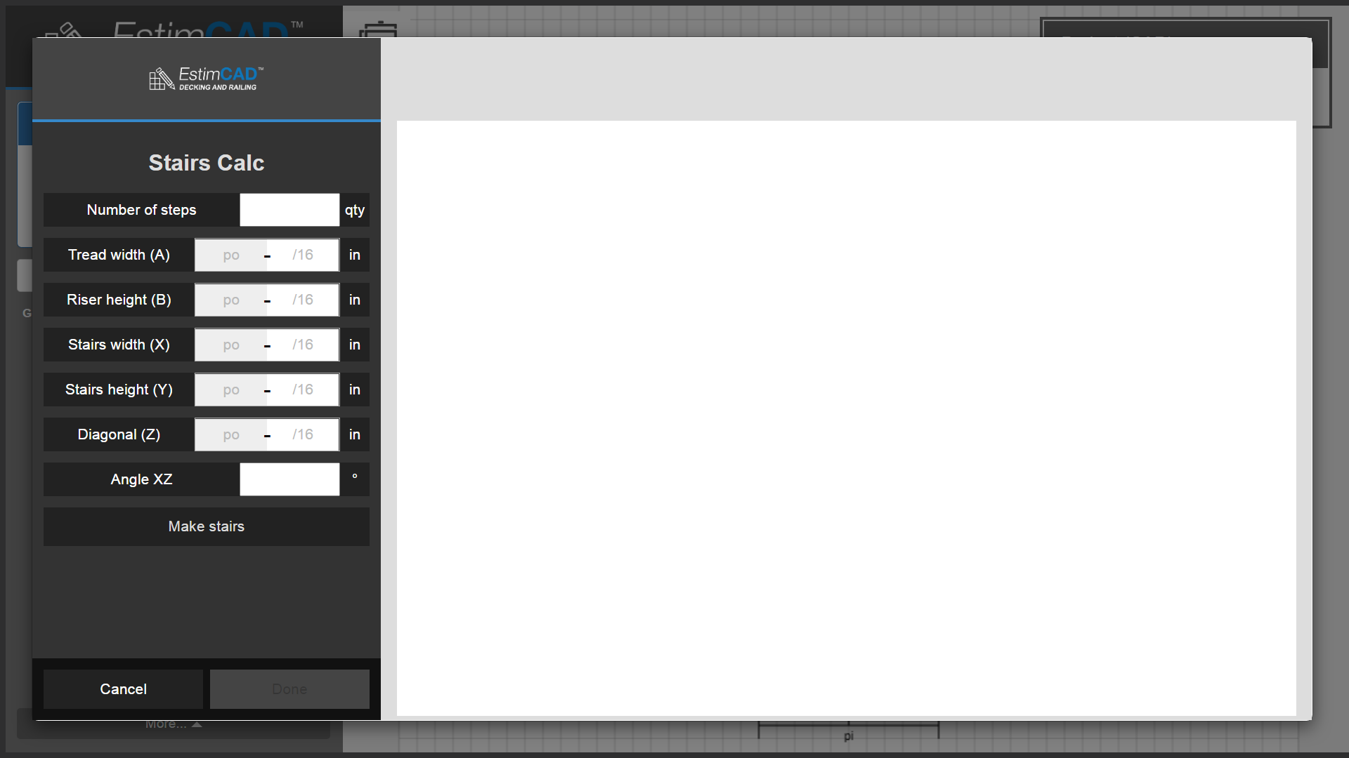
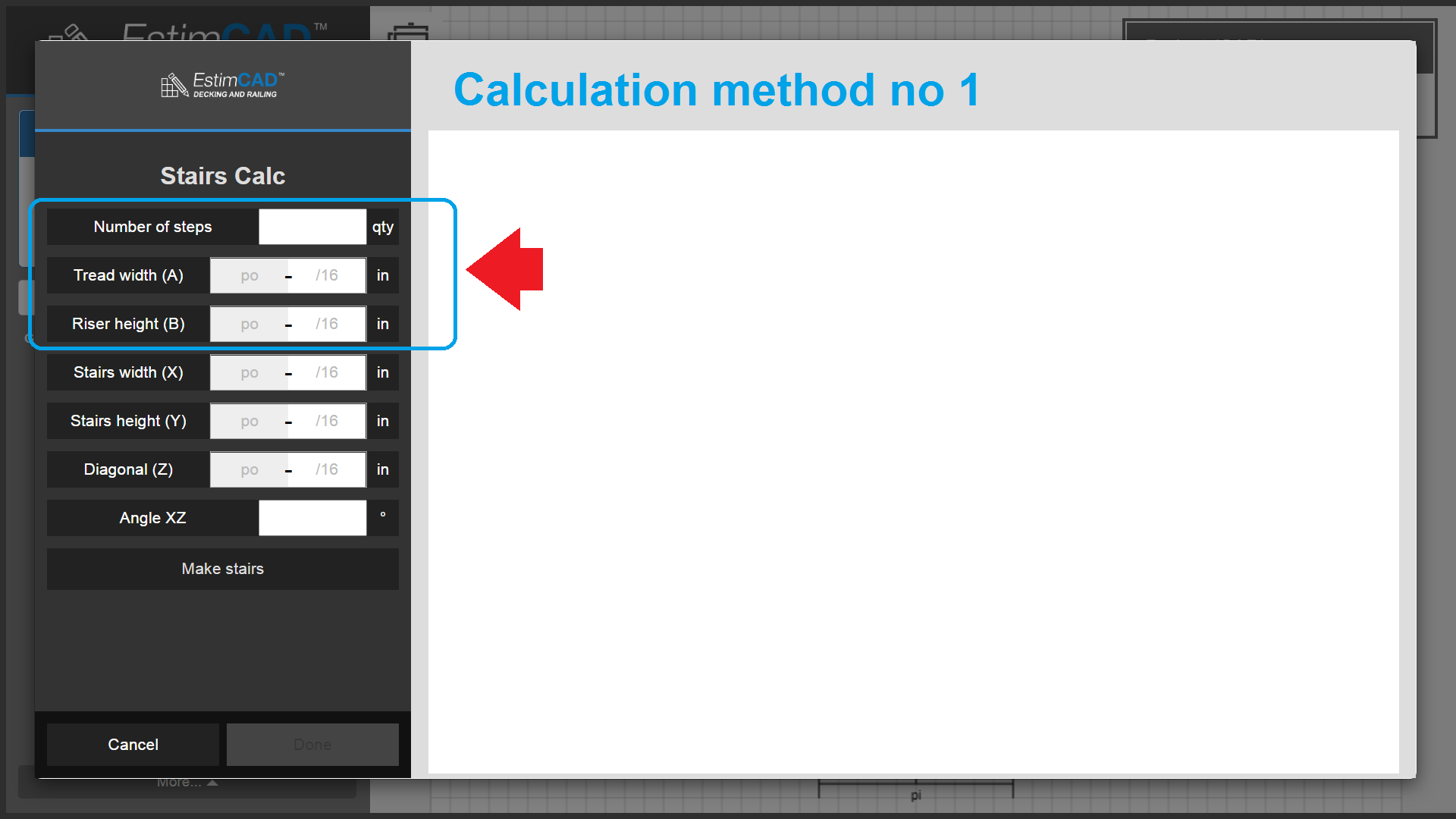
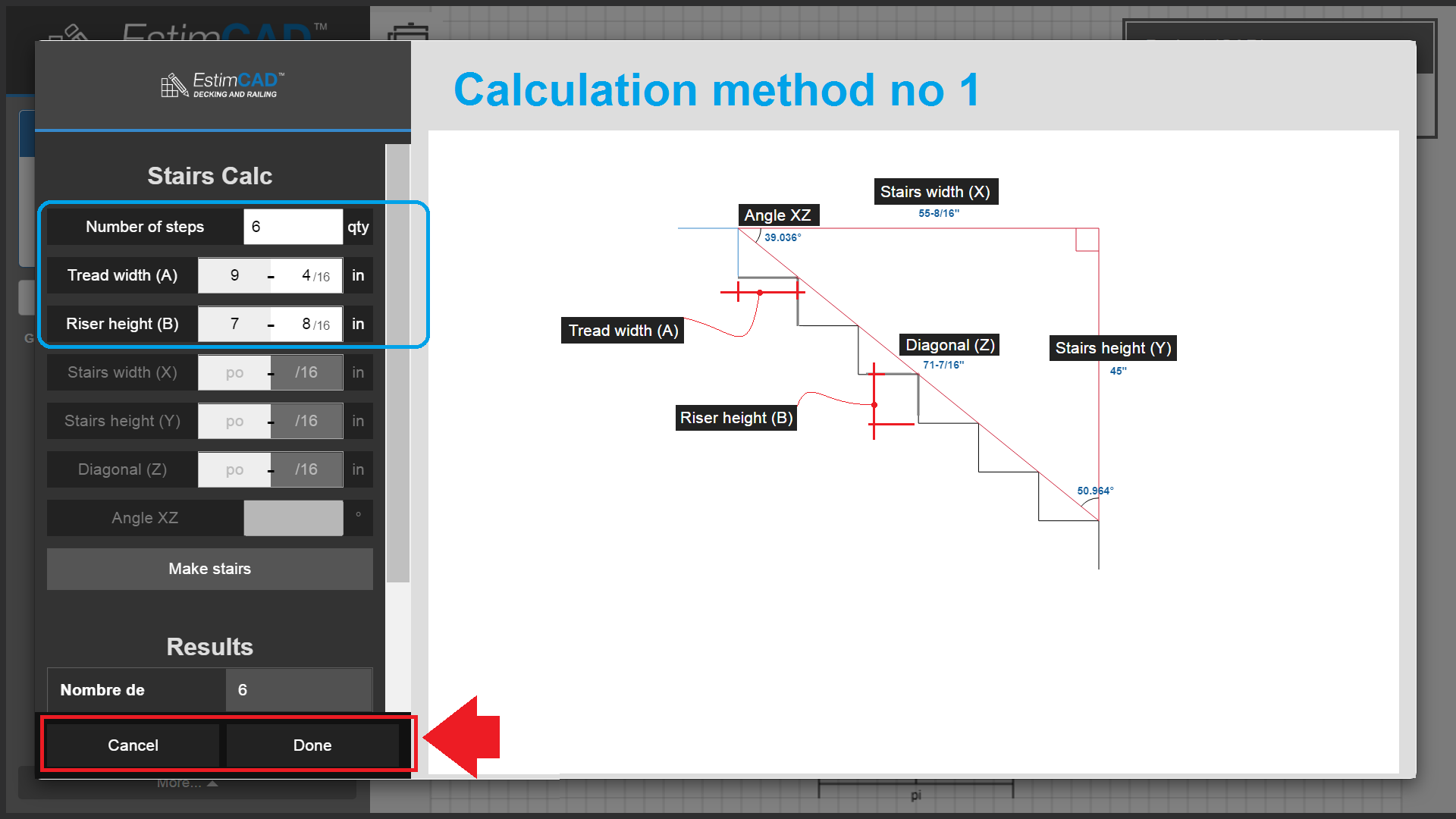
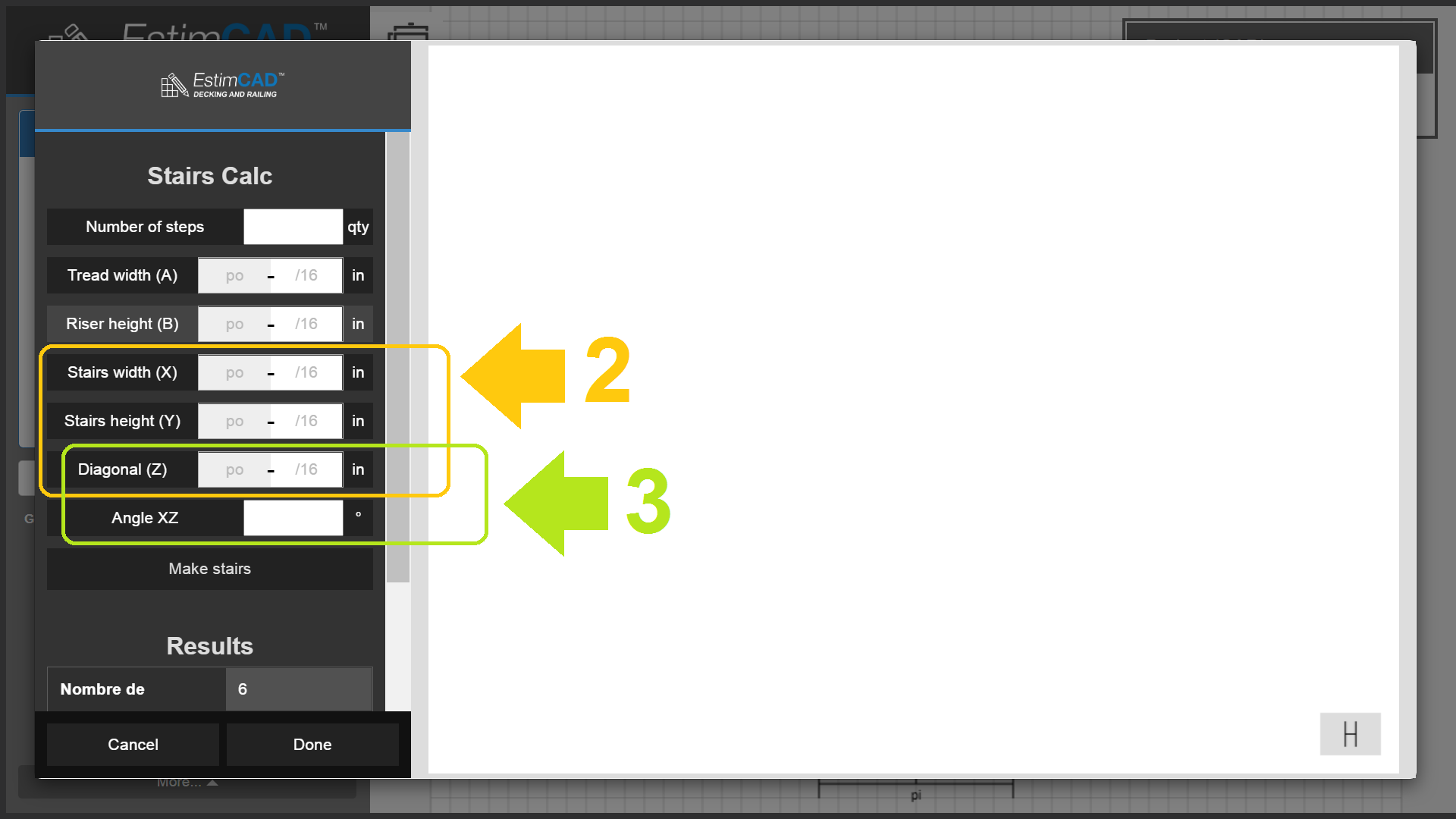
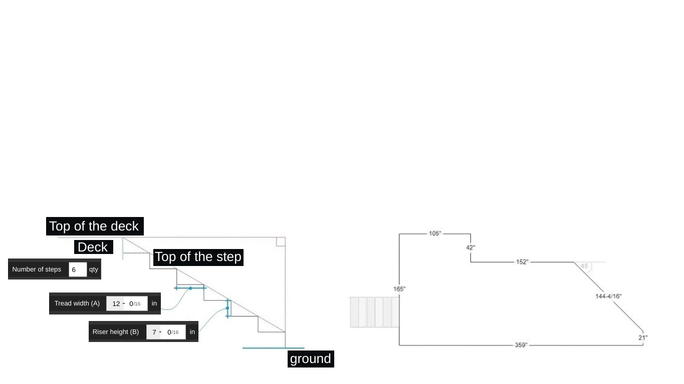
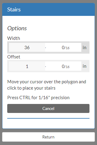
The stairs configuration utility will appear. It allows you to enter a few combinations of measurements depending of what you have access to.
Options :
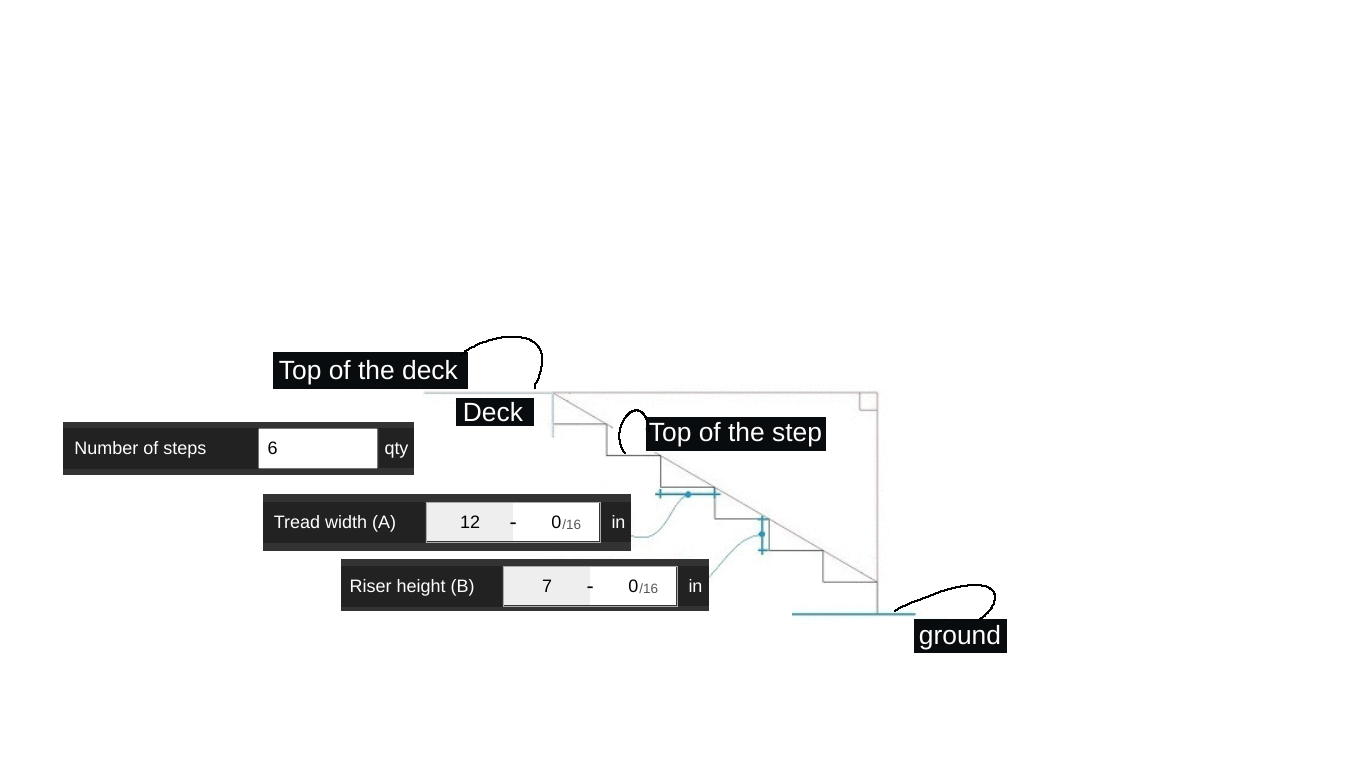
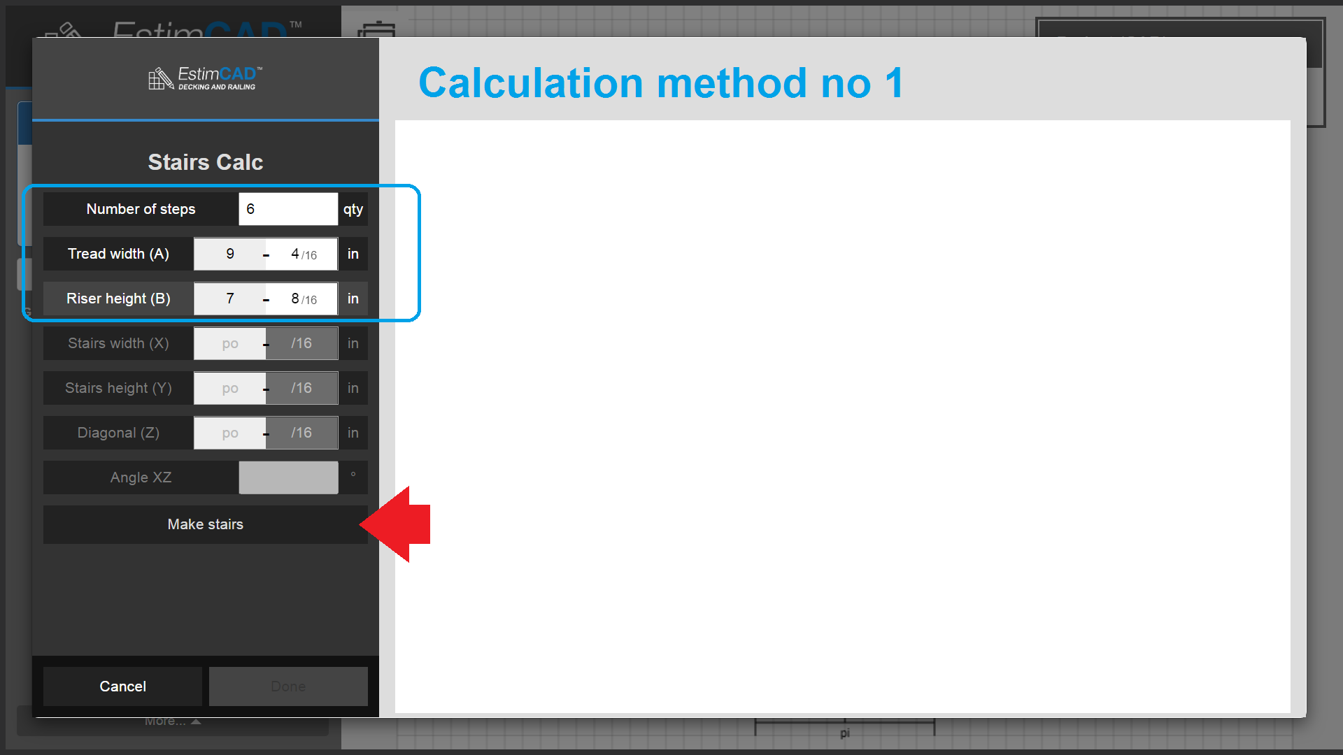
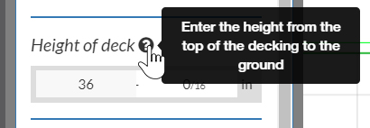
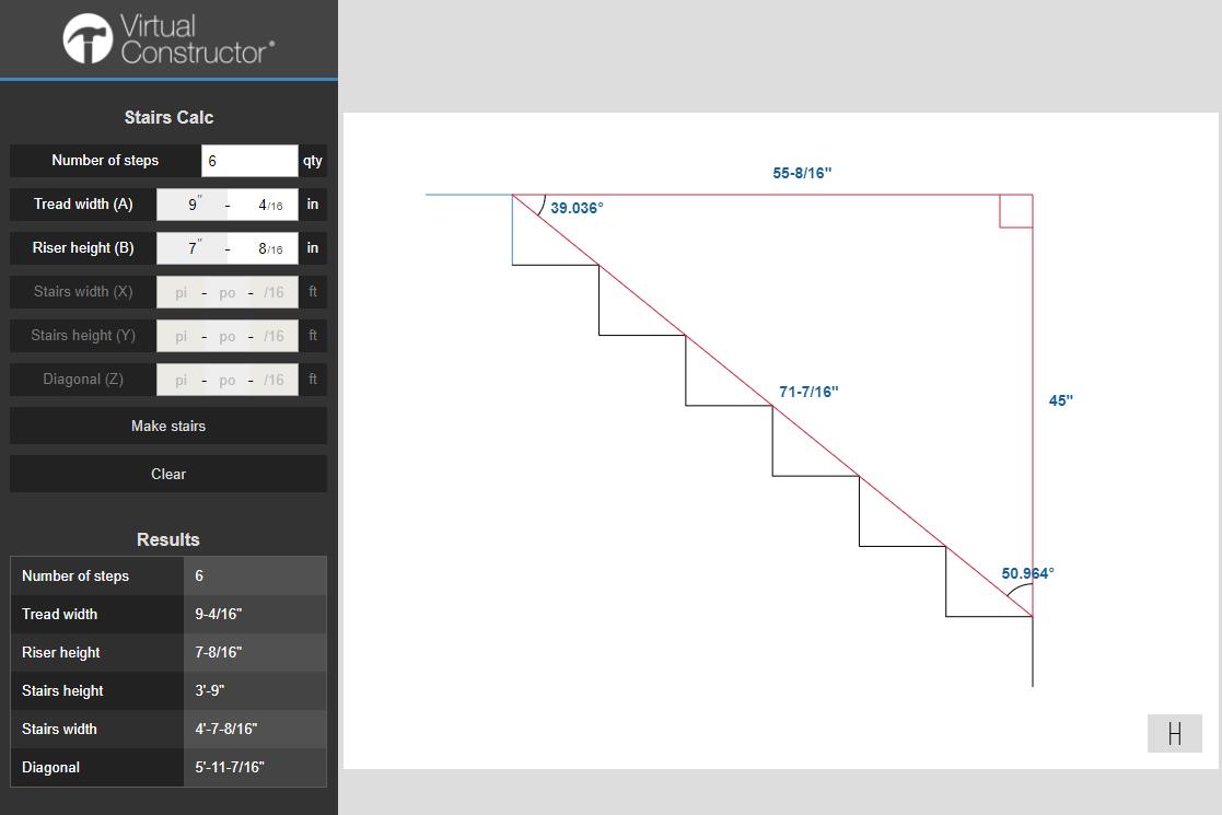
Enter how many steps and their step height and width and the software will compute the missing XYZ and angles information. (image below).
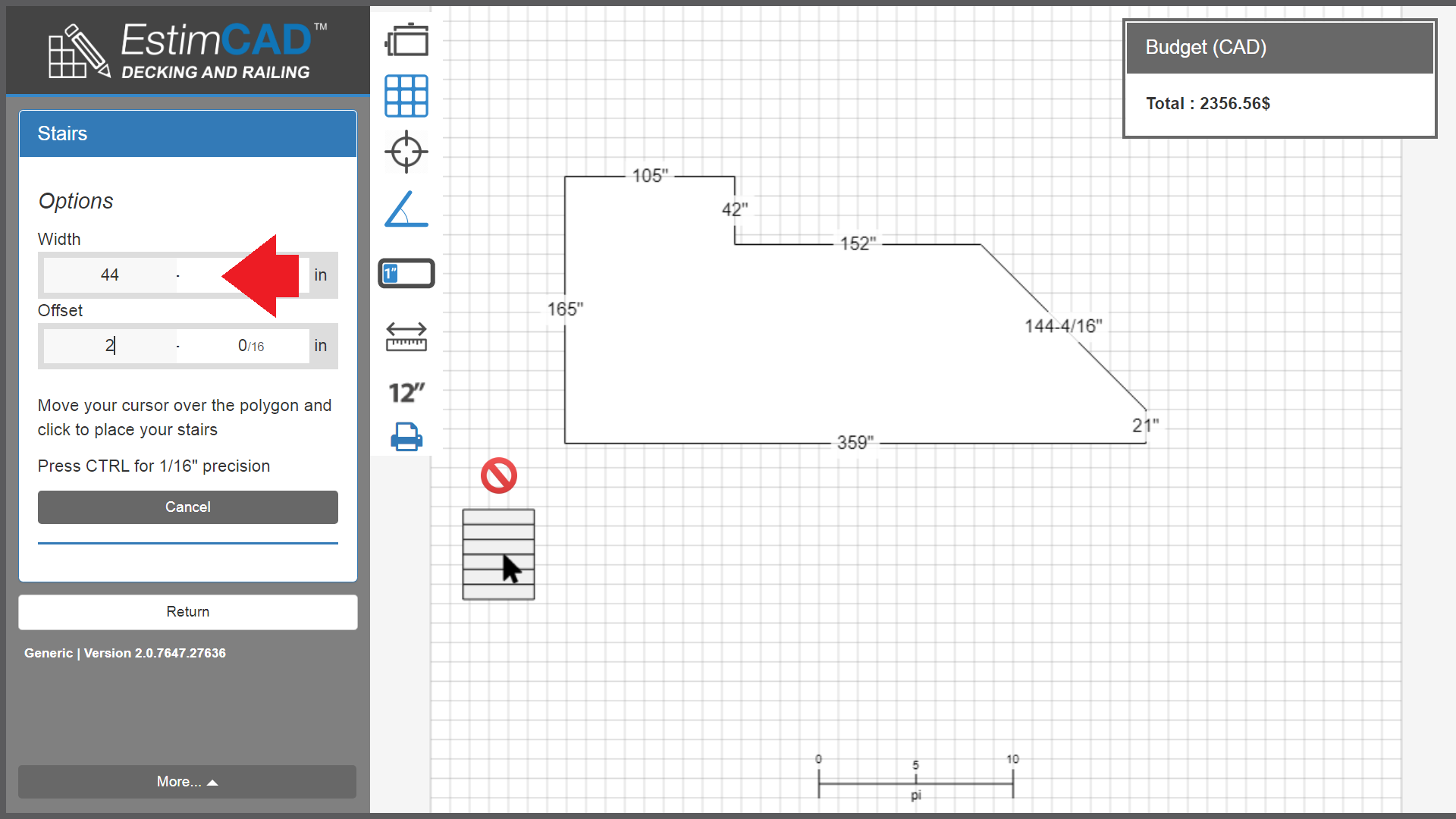
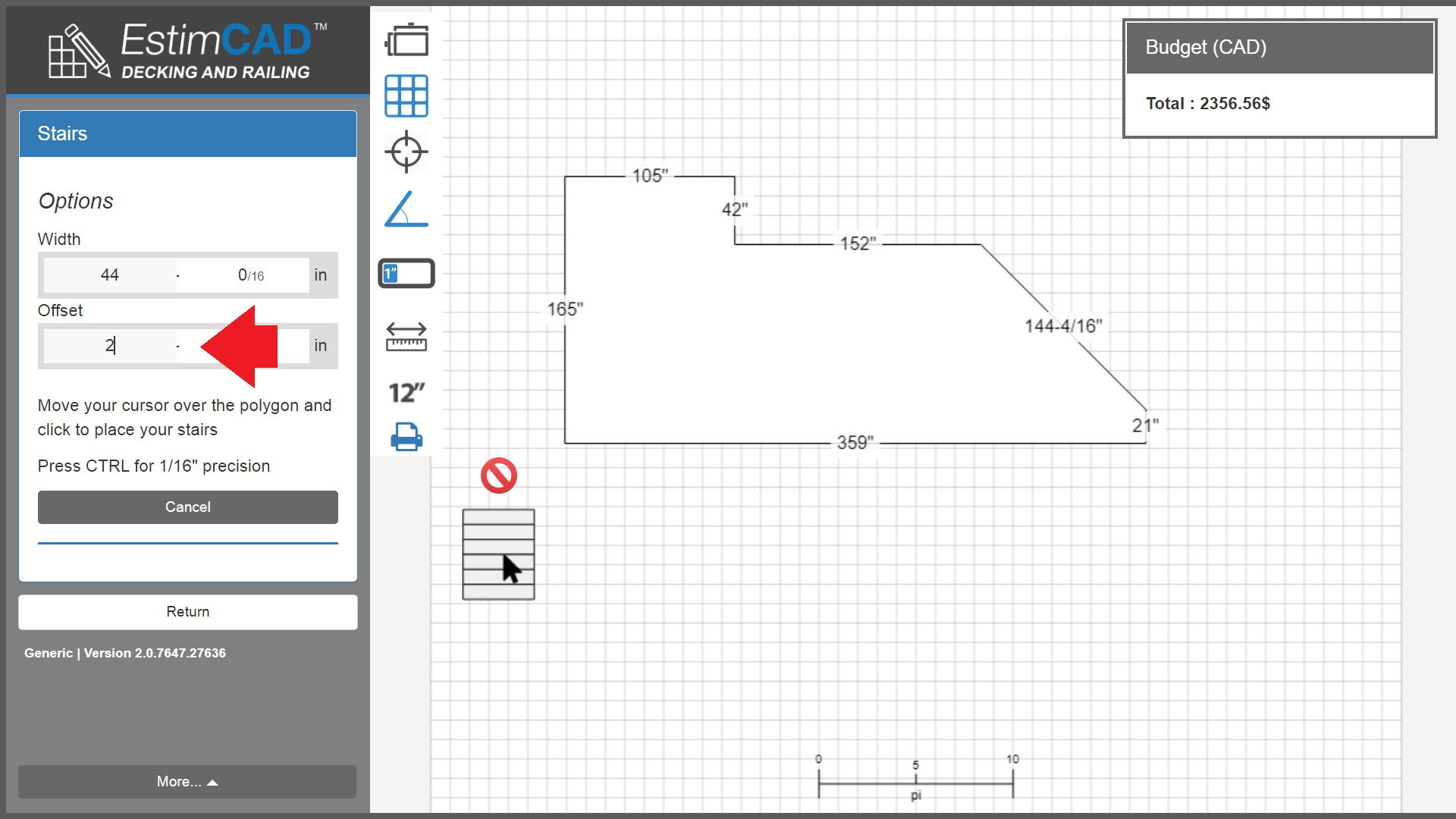
Then, back in EstimCAD's main interface, enter the width of the stairs. Example: 36".
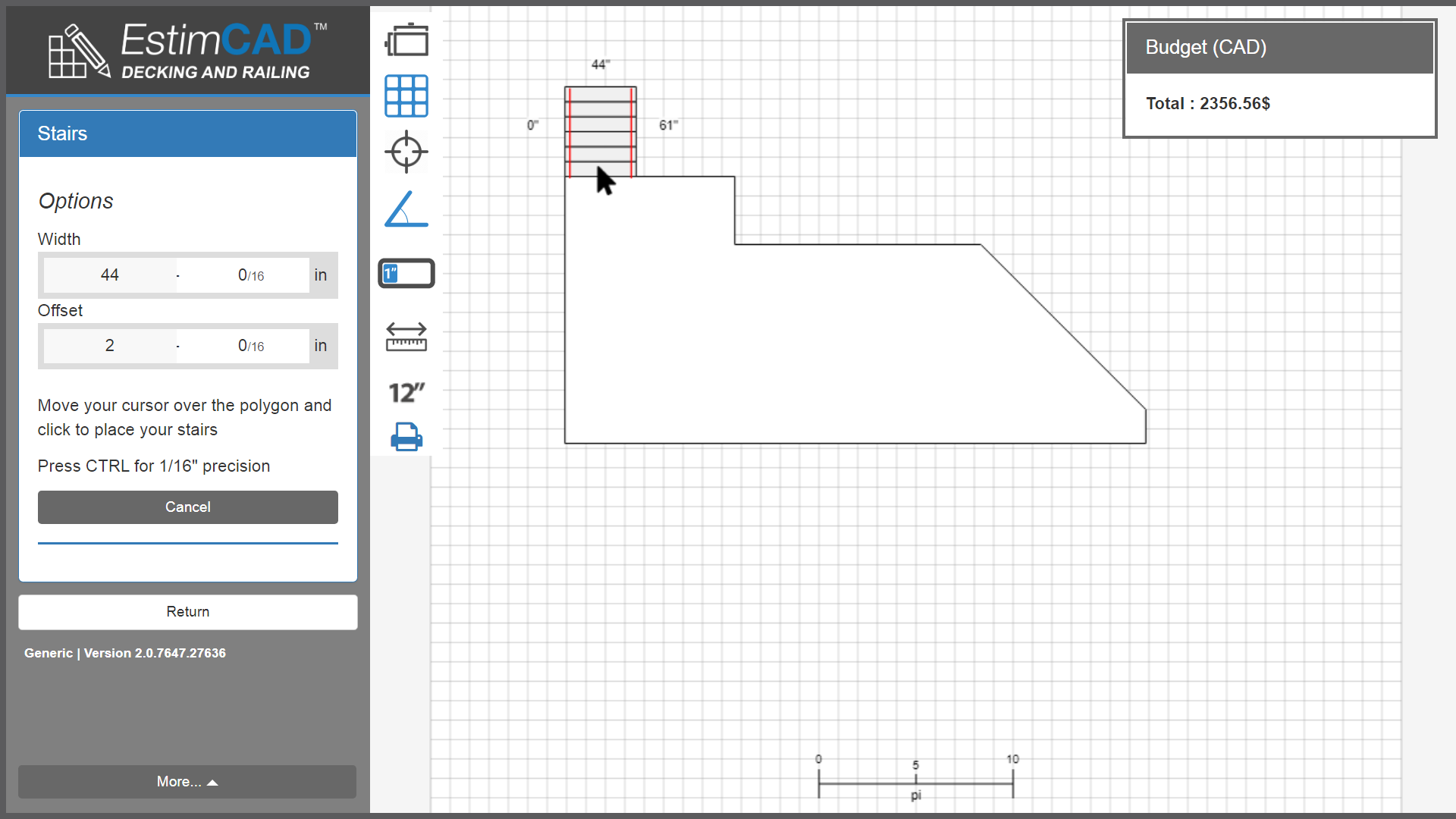
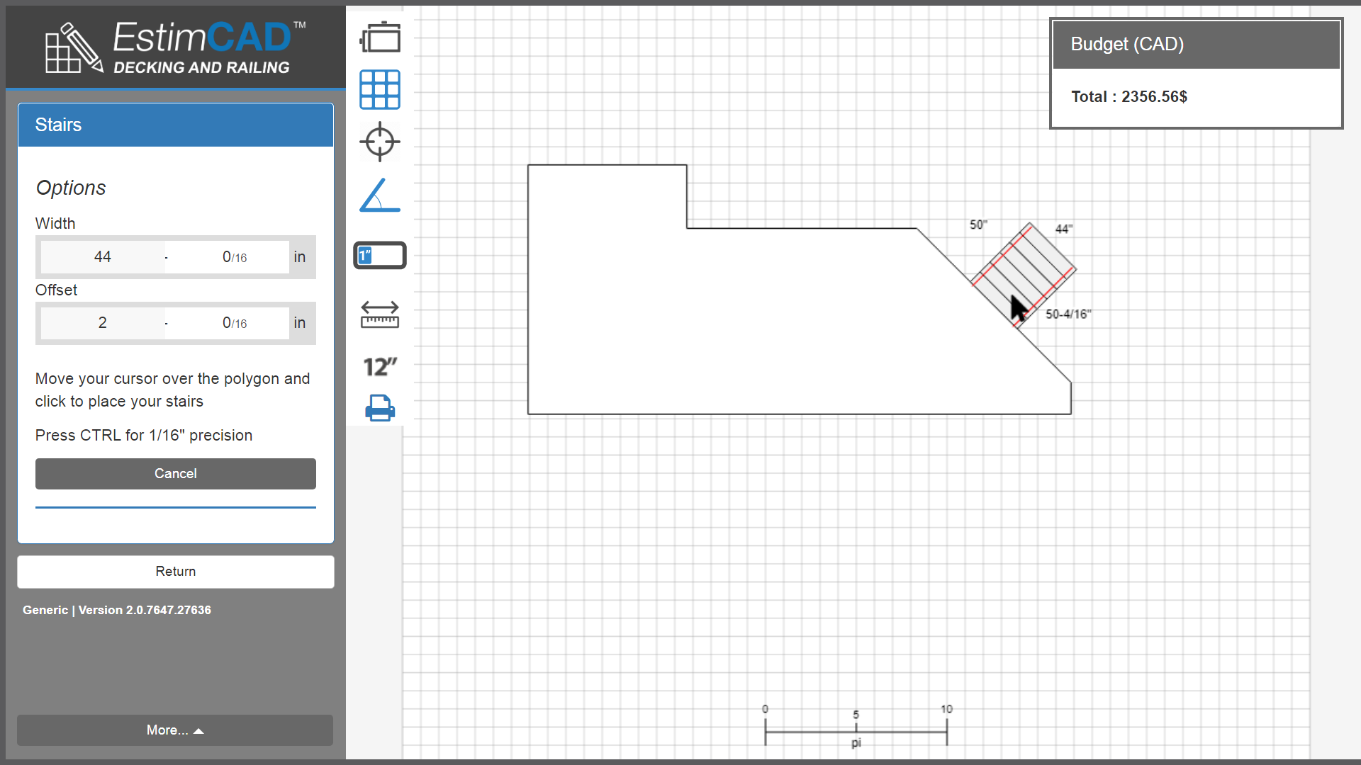
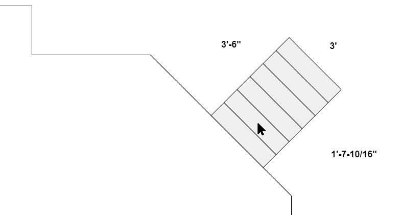
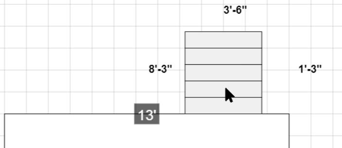
Finally, move your mouse over the plan and place the stairs by clicking.
At 3’-6" of the left corner and 1’-7- 10/16" of the right corner, a 3’ (36") stair set.
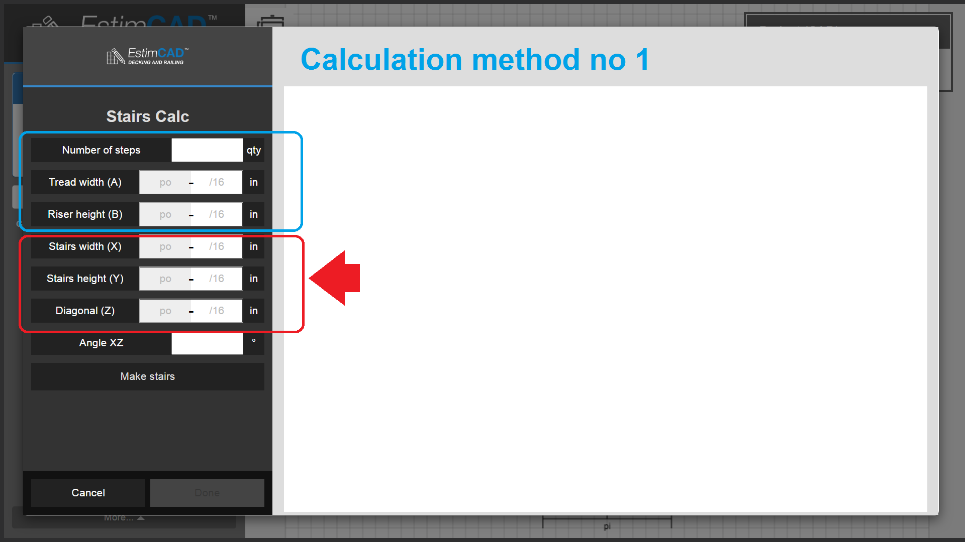
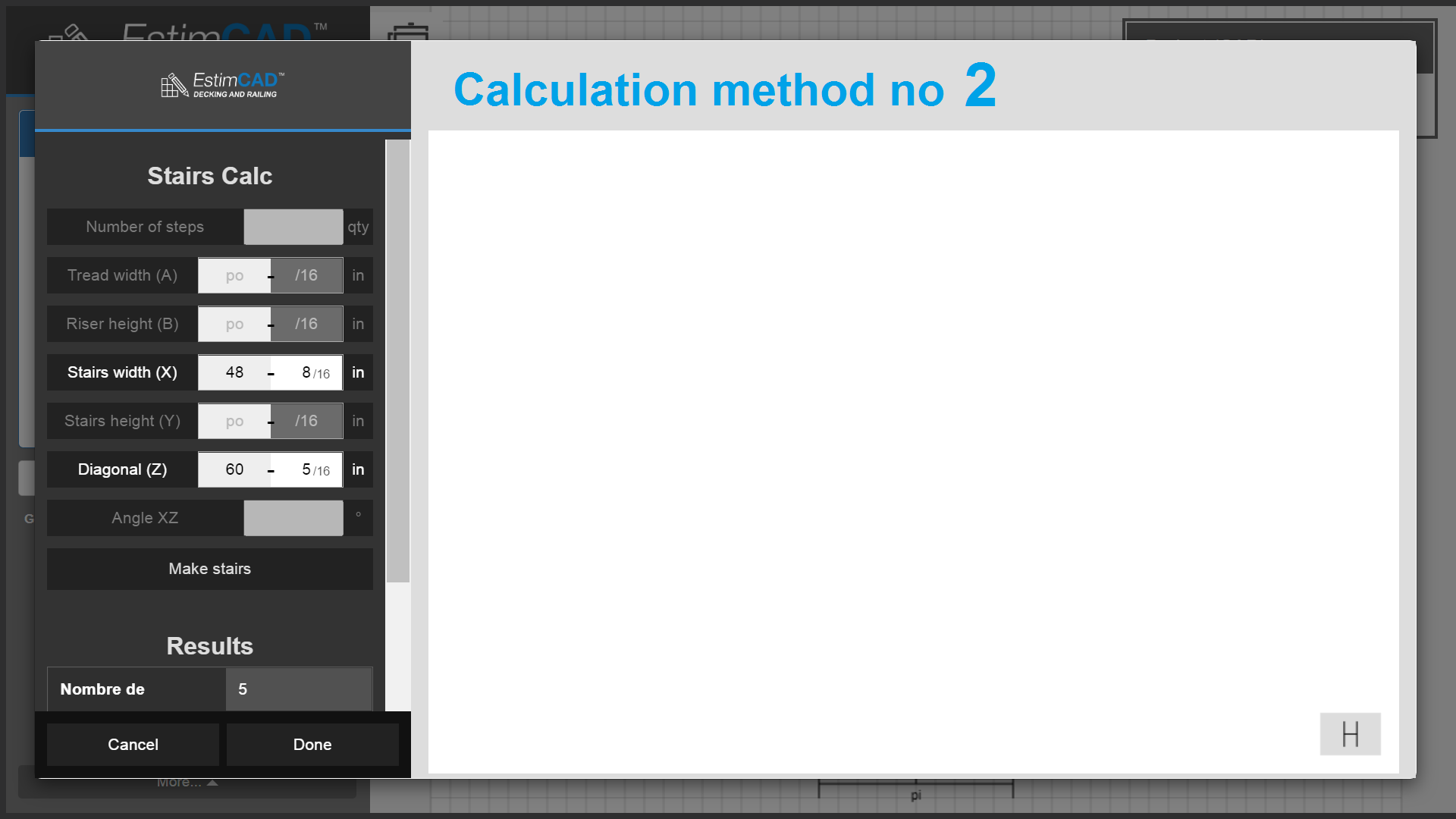
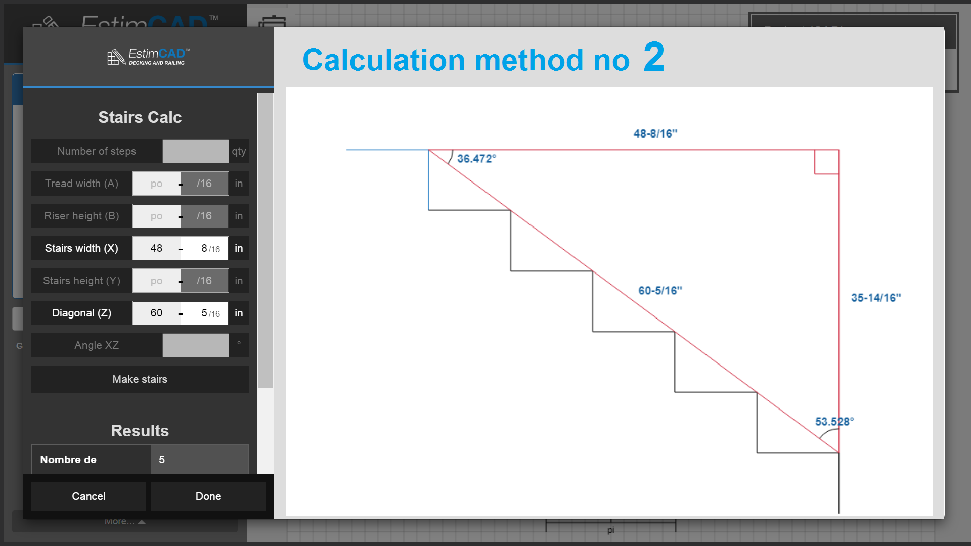
You could also have entered 2 of the 3 in X, Y, Z inputs and the software would have calculated the same.
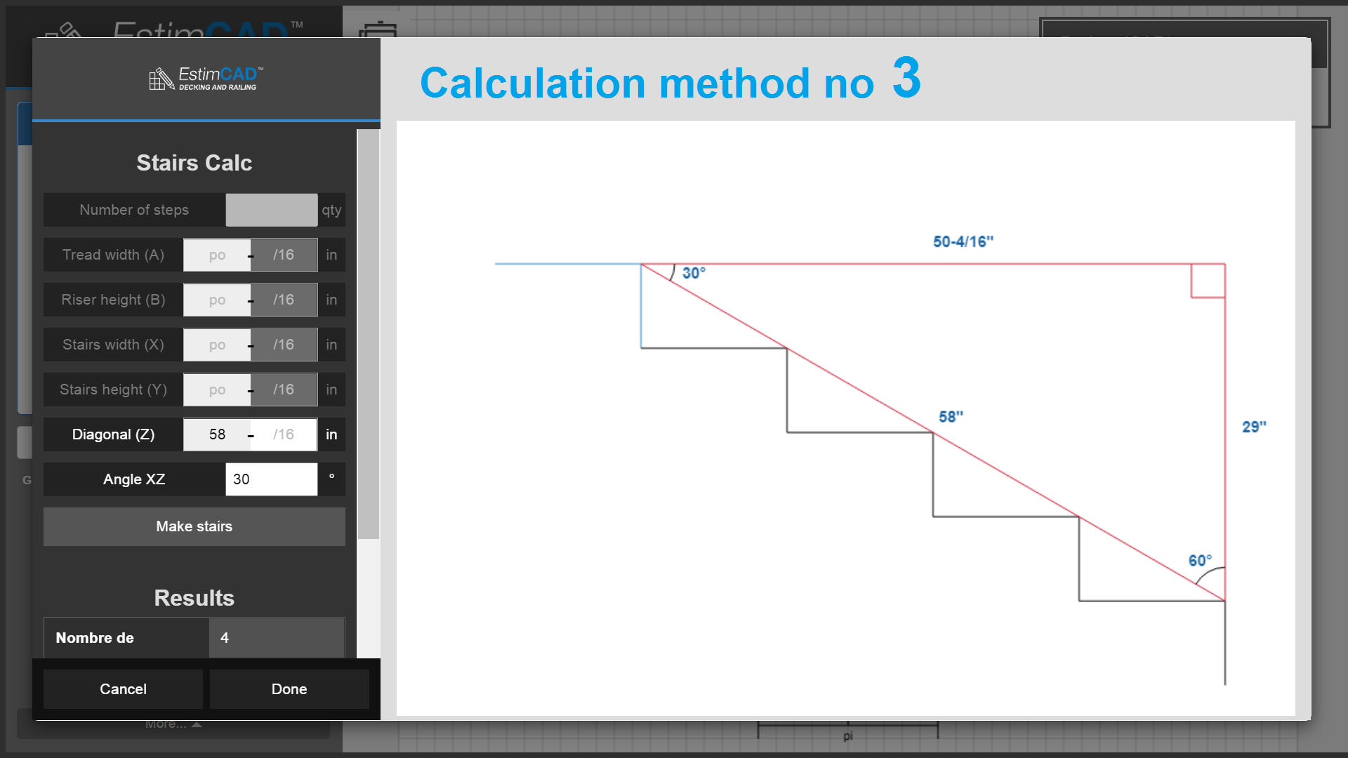
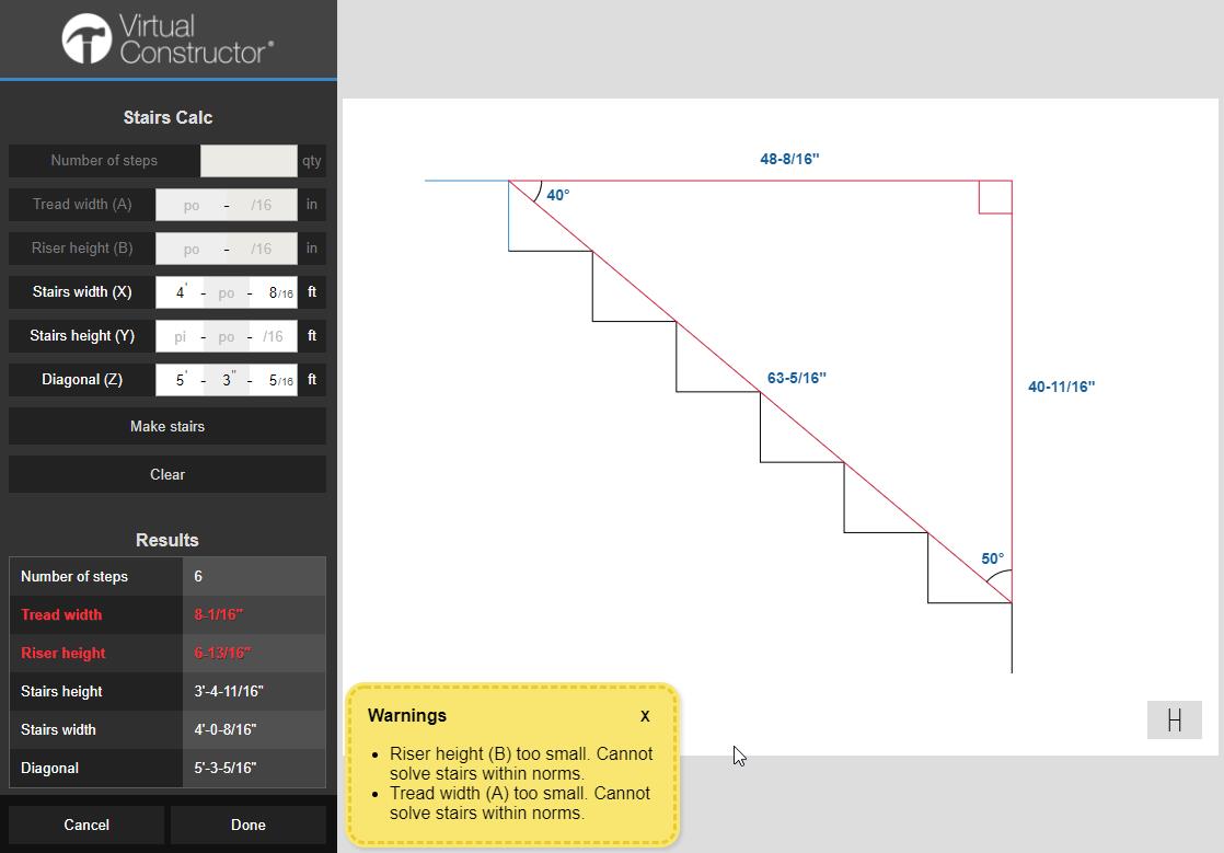
In the image below, we have entered:
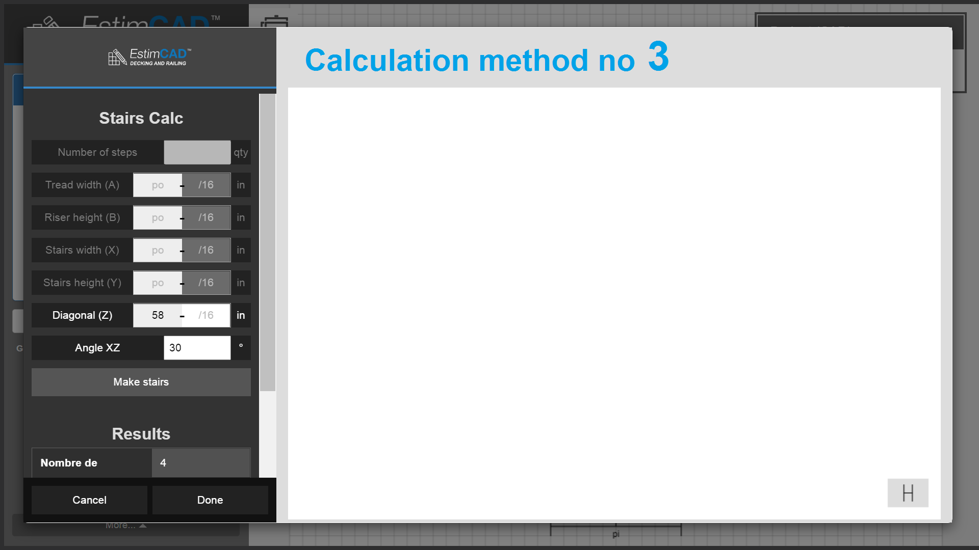
You could also have entered the angle of the stairs and one of the following measurements : Height, length, diagonal.
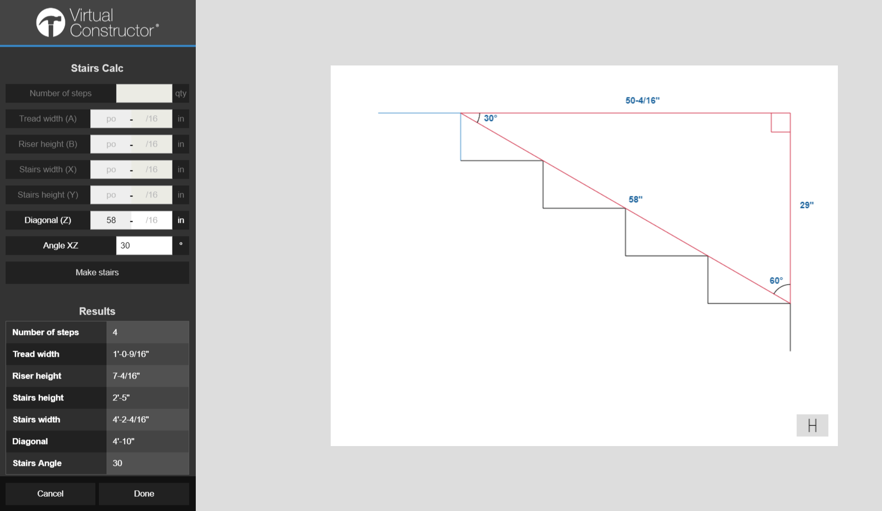
These measurements are relative to the stairs, not the whole deck. Therefore "height" is not the deck height from the ground but only the stairs height.
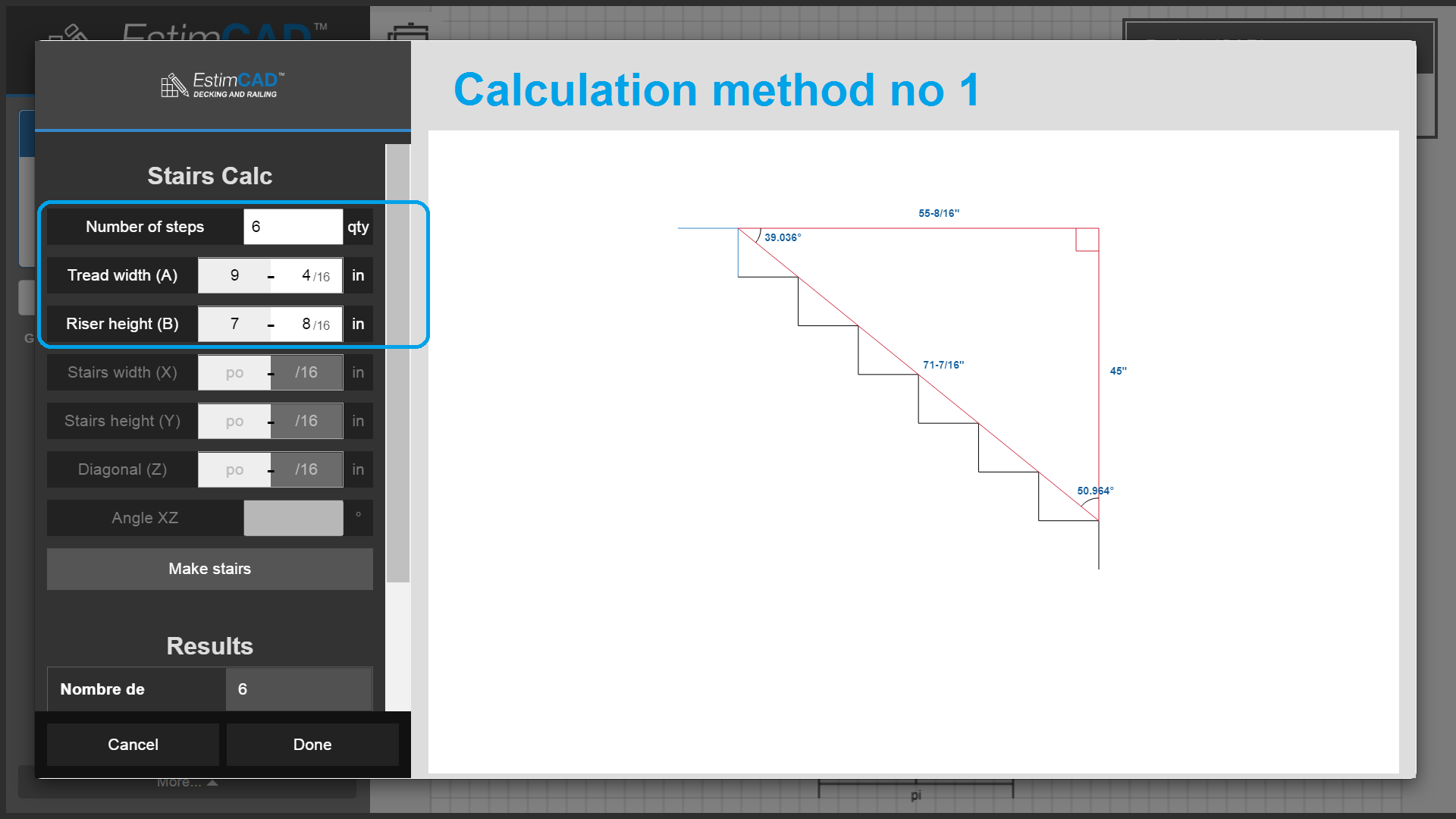
You can still see all the displayed information: Angles, A, B, X, Y and Z.
The results will always be highlighted in red when out of standards.
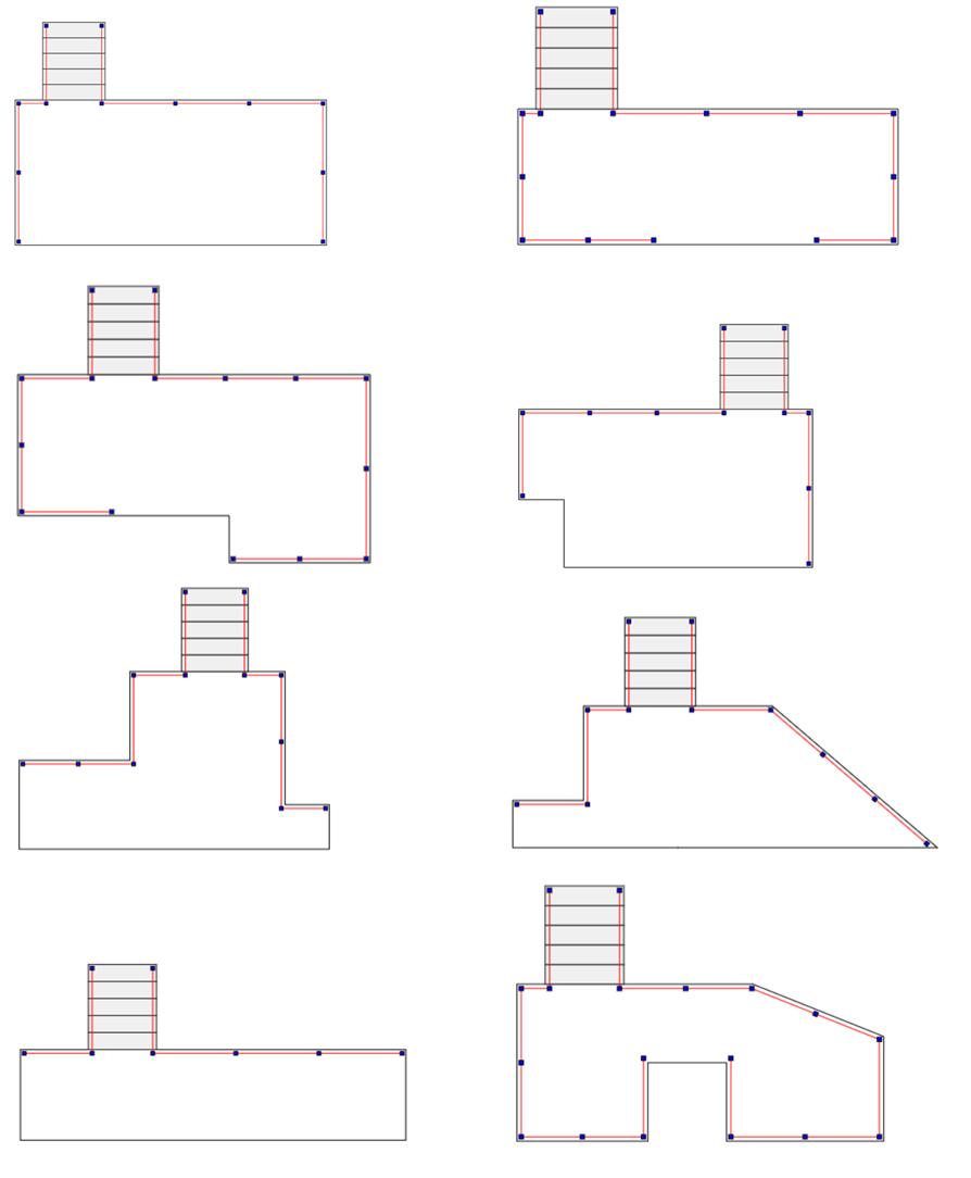
Here are some examples of stairs you can create and insert with the CAD.
 |
 |
 |
 |
| Decks on 2 different heights | Imitates corner stairs to calculate railings |
 |
 |
| Deck receiving another deck above it | Against a wall so no railings |
 |
 |
Just like you can draw the deck outline with 1/16" precision, you can place stairs with the same precision. Just press and hold CTRL at the nearest measurement and move your pointer up and down the precision picker, then click to place.
Hold CTRL to place stairs precisely
Let’s say you want to place your stairs at 8’-3-9/16’’. Bring your stairs to 8’- 3’’ …
… and PRESS AND HOLD CTRL to display the precision selector. Move your mouse along the selector vertically and click to accept the measurement. You can then release CTRL.
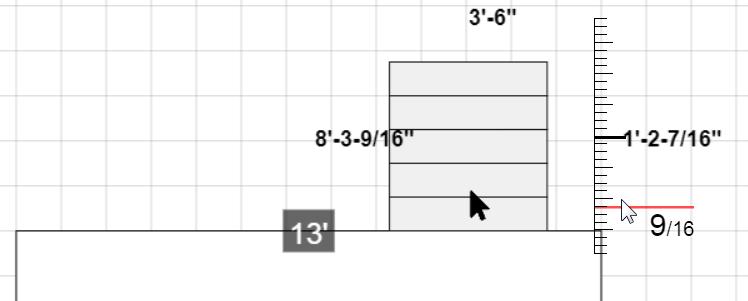
Holding CTRL allows you to release it in case you your initial measurement was incorrect. In this case, if after pressing CTRL we think we need to place it at 8’-1” instead, you can then release CTRL and move your stairs again.
First you need to do this TRAINING on
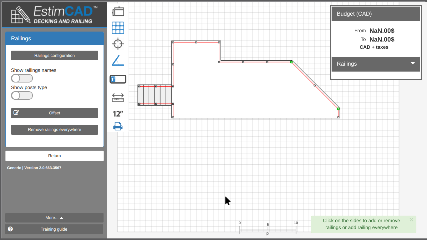
Create and place the railings
Then, continue with all the different explanations below.
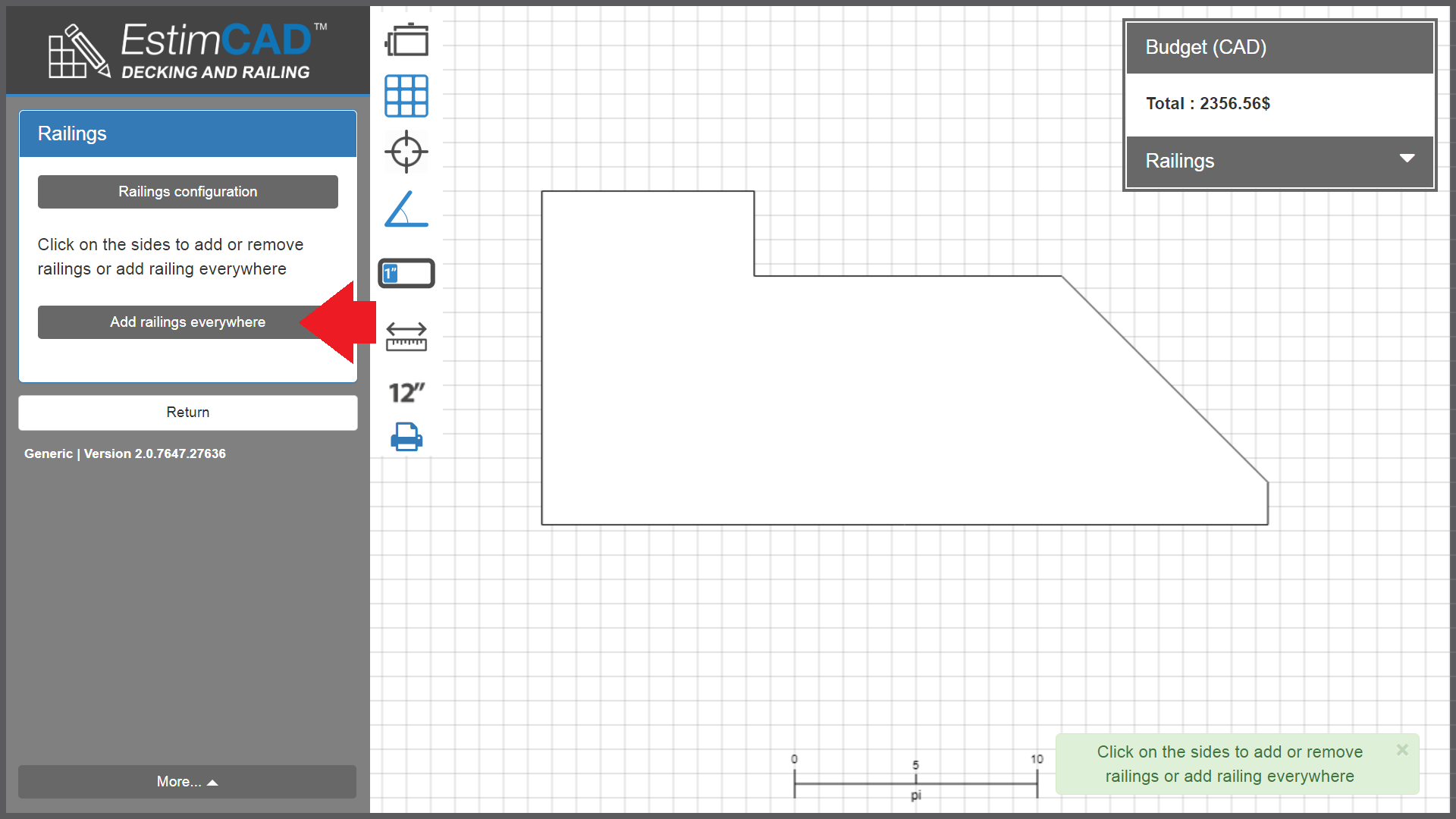
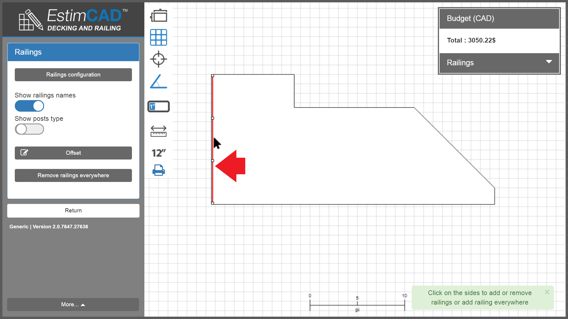
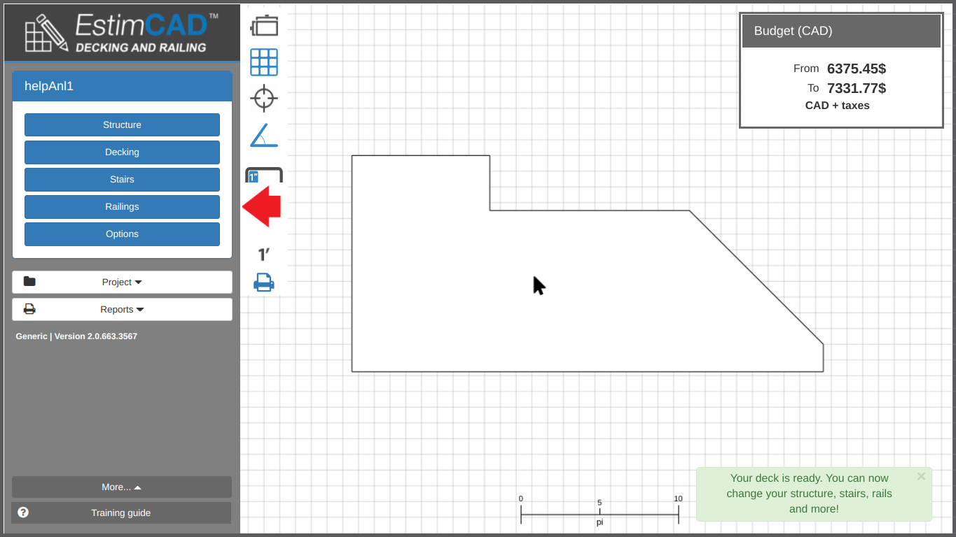
This function allows you to create and place the railing on the outlines of a deck plan and its stairs, as illustrated in the following slideshow.
The railings insertion and calculation functionalities make it possible to estimate the exact length of the rails to the nearest 1/16 ”and to offer quantity results that are optimized and in addition at the best price.
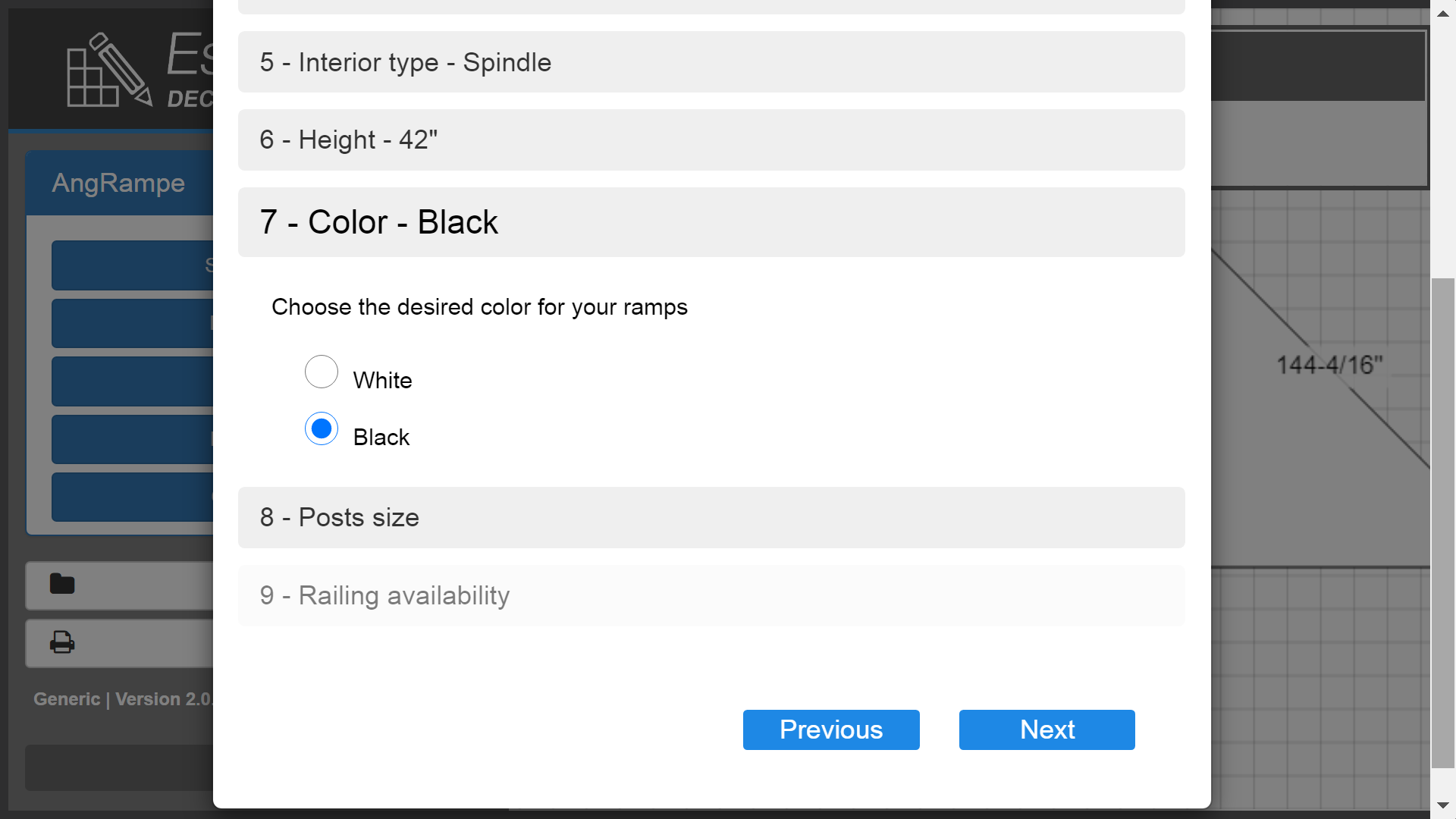
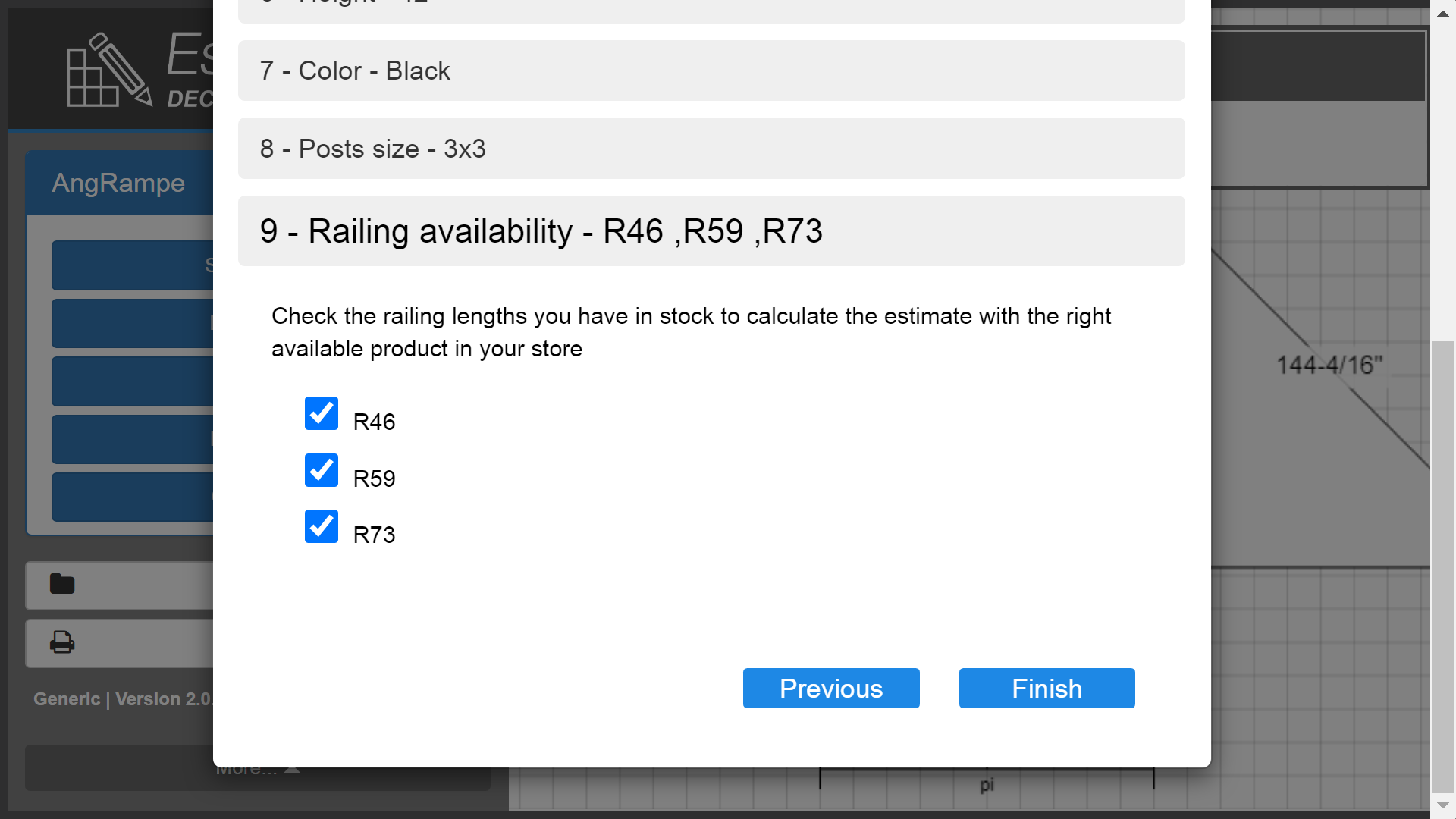
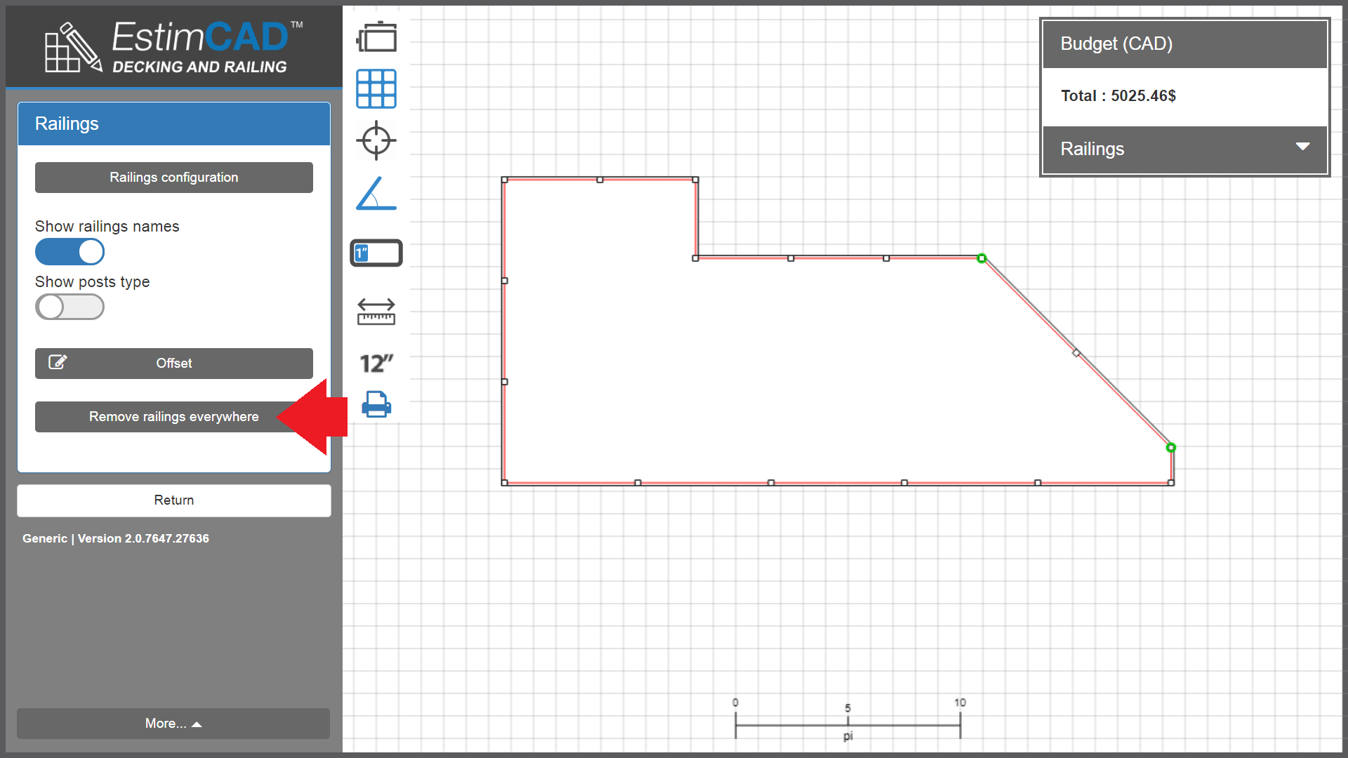
You can always choose according to the available inventory. The latest "Railing Availability" feature allows the user to make product choices based on the inventory held in the store on the day of purchase.
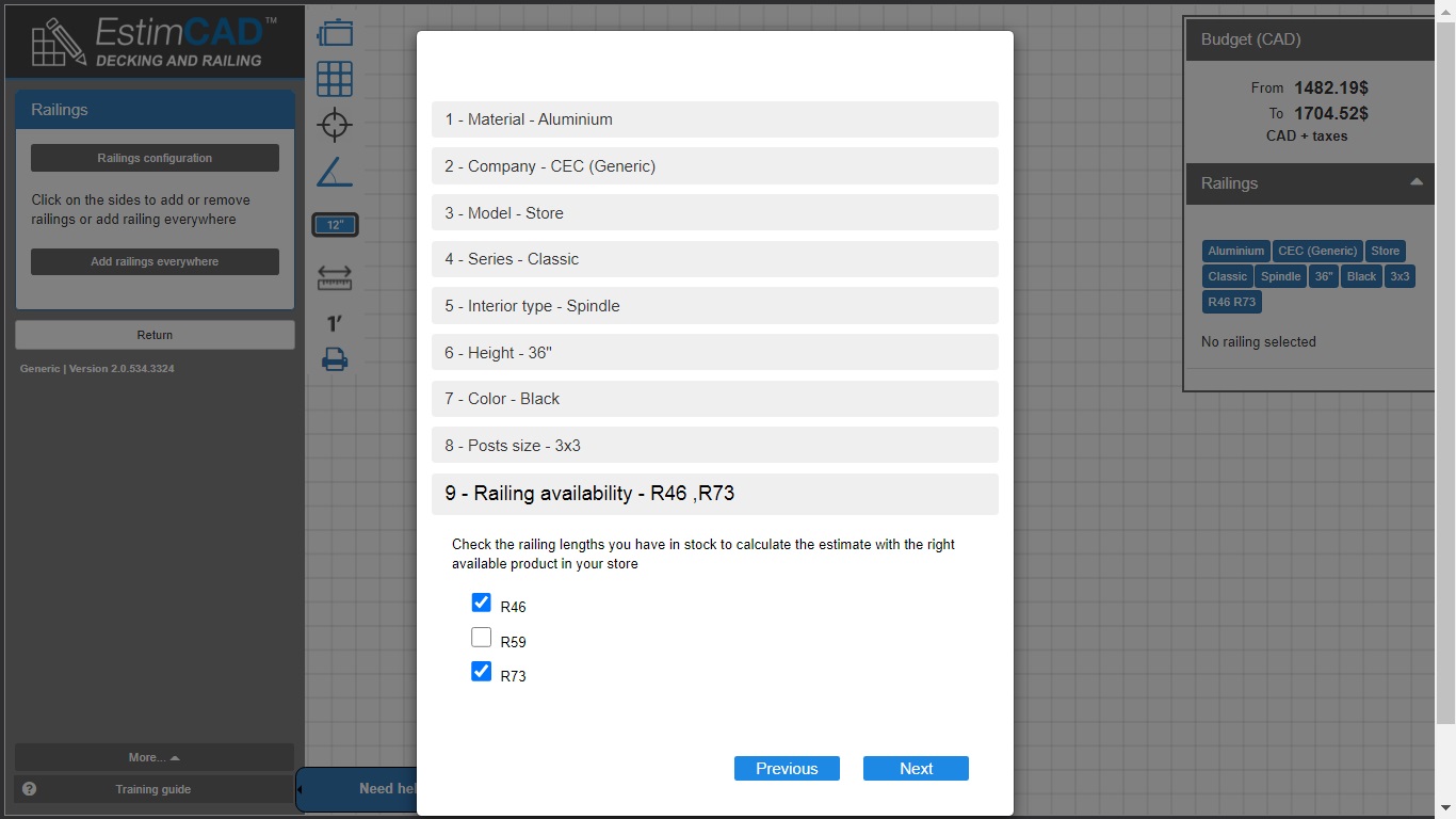
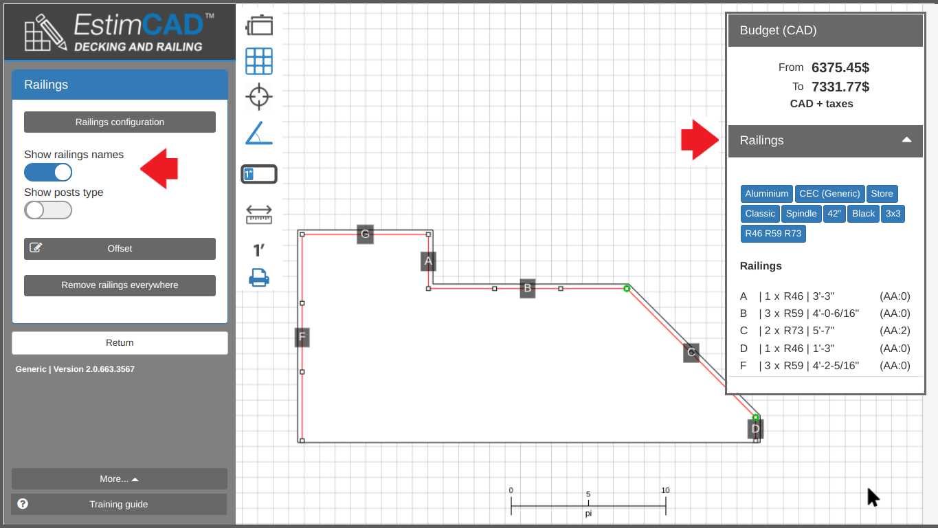
Here is an example, if there is no more R59 (59 inch length) railing model in inventory, the user will not select R59 and the application will calculate the quote automatically at the best price, with only the models from R46 and R73 railings, as shown below.
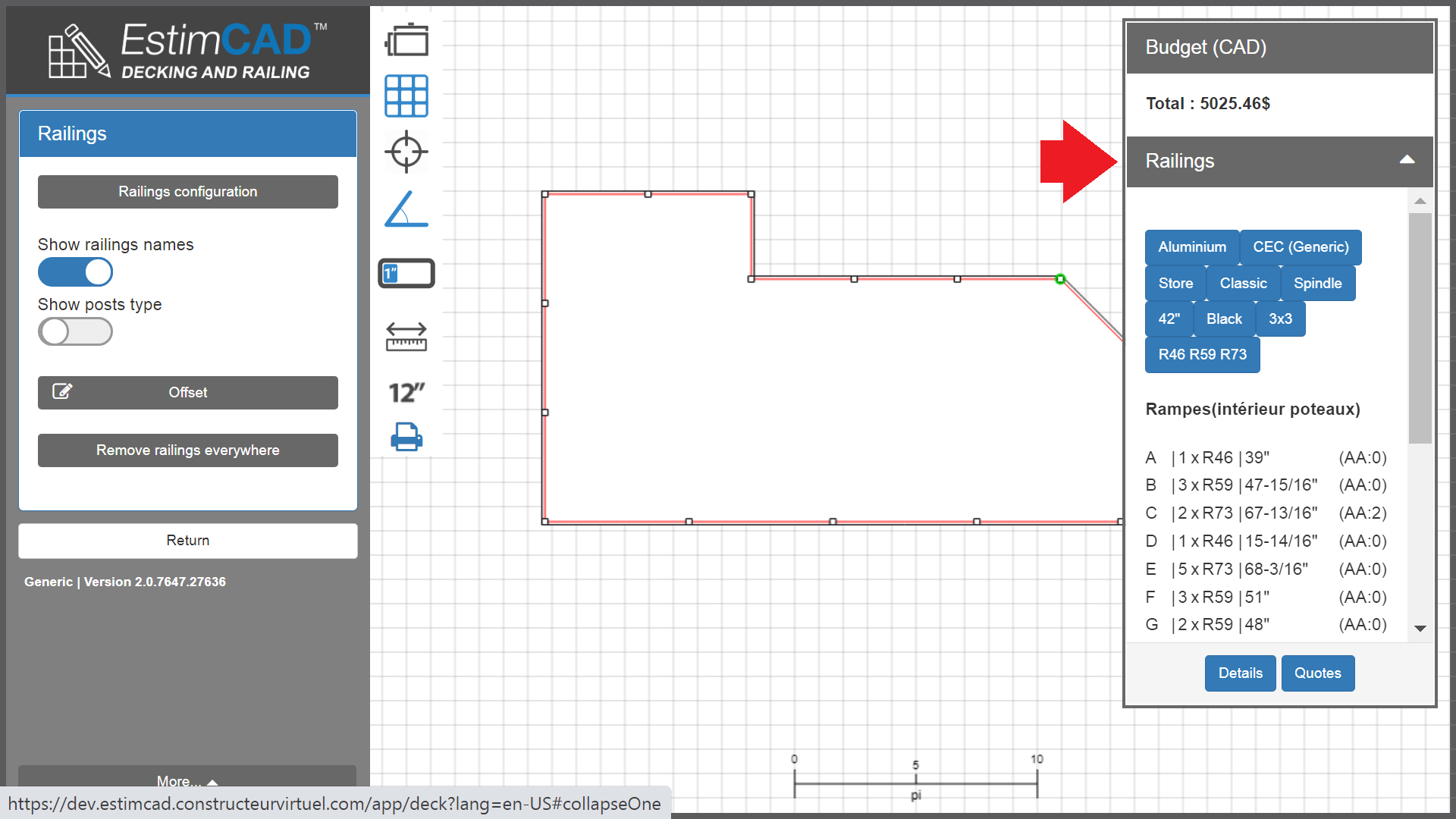
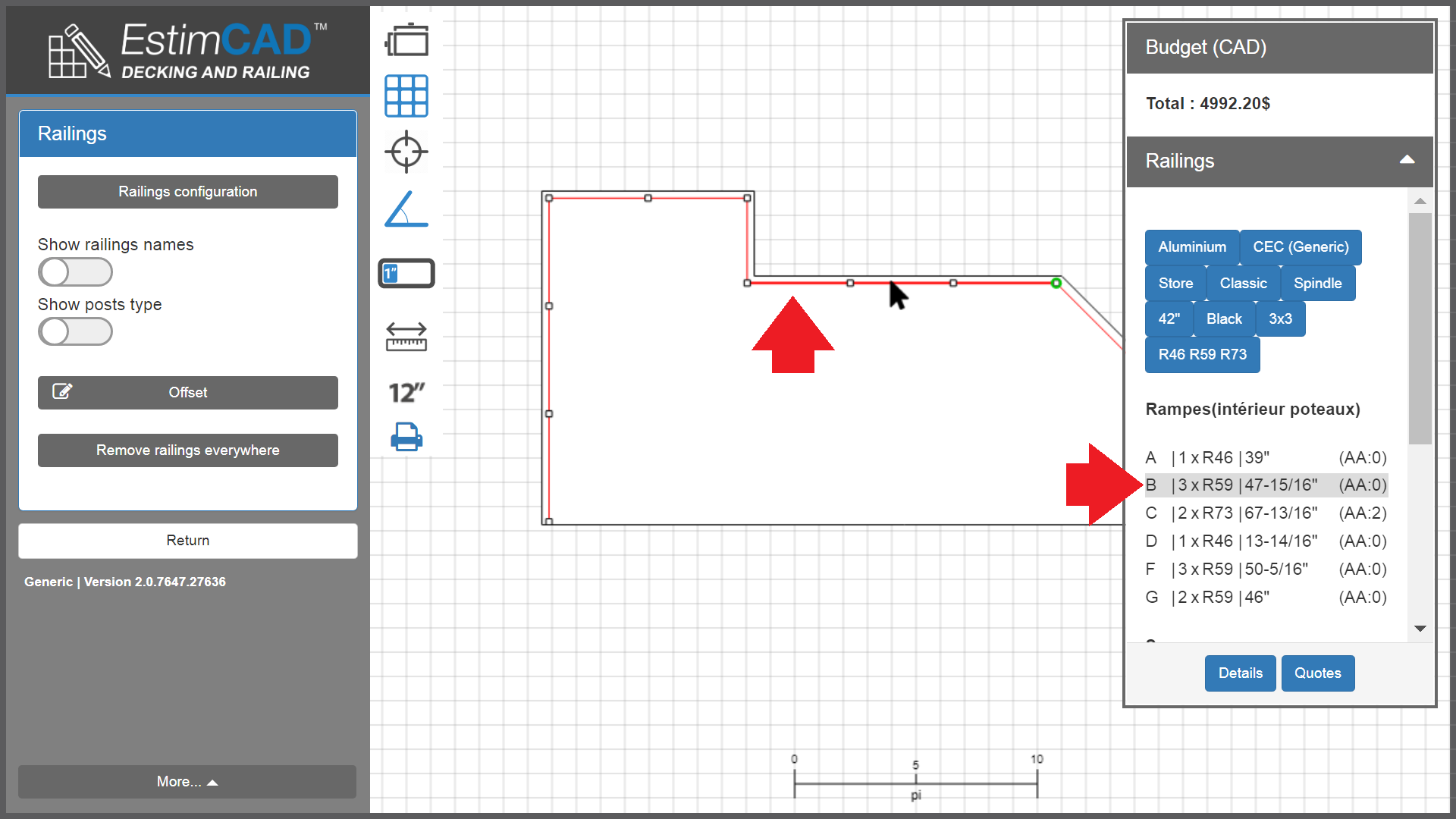
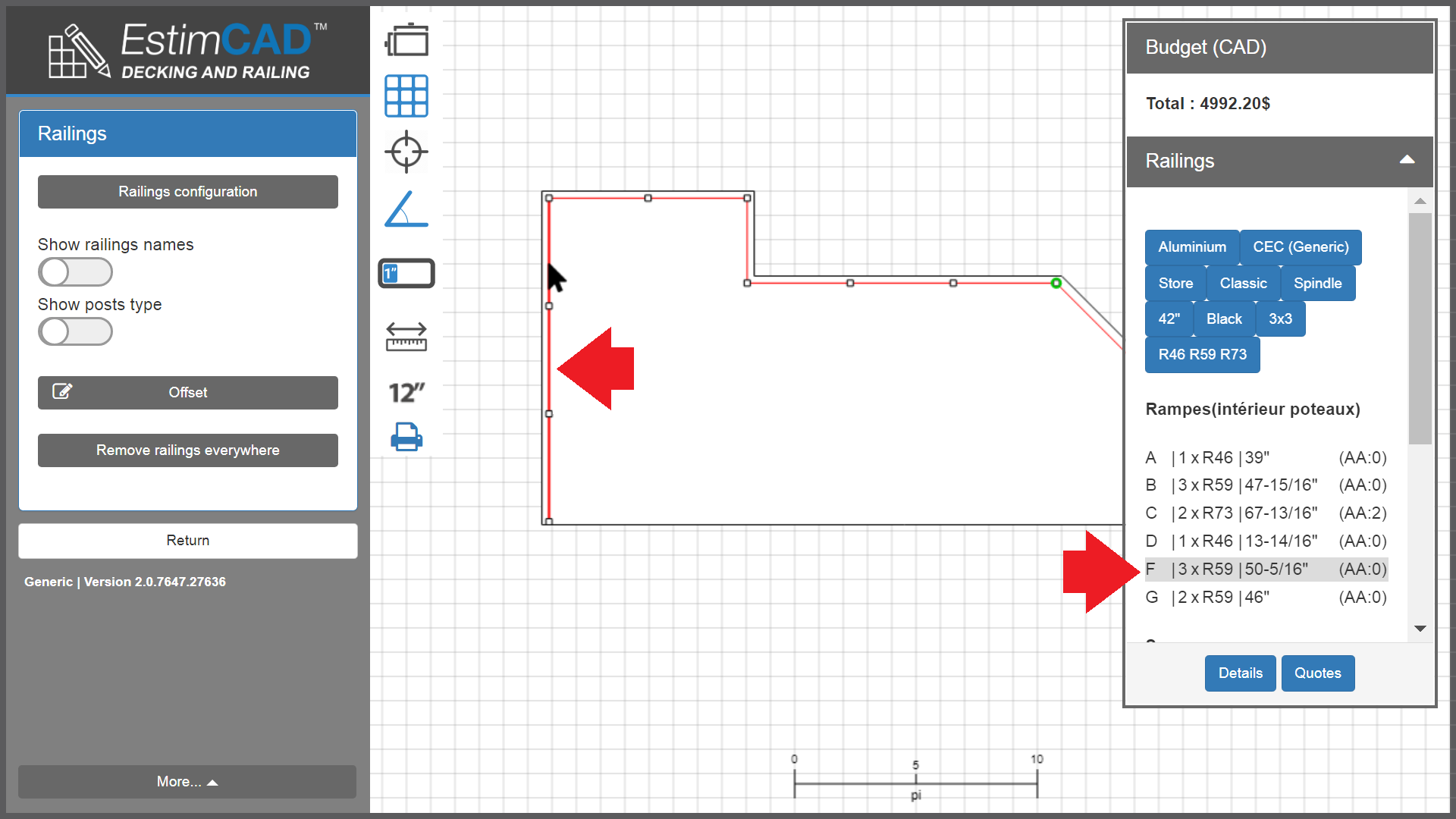
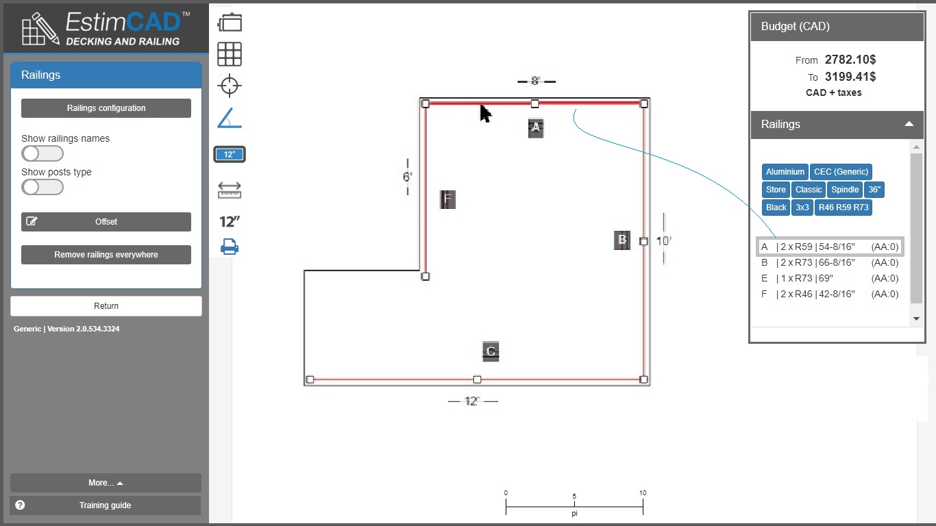
The following example illustrates the calculations that are optimized with R46, R59 and R73 railings models.
For side A = 8 ", B = 10", C = 12 "and F = 6"
So the best A side result of 8’ (96'') will be 2 x R46,
the best result on side B of 10 '(120' ') will be 2 x R59,
And so on …
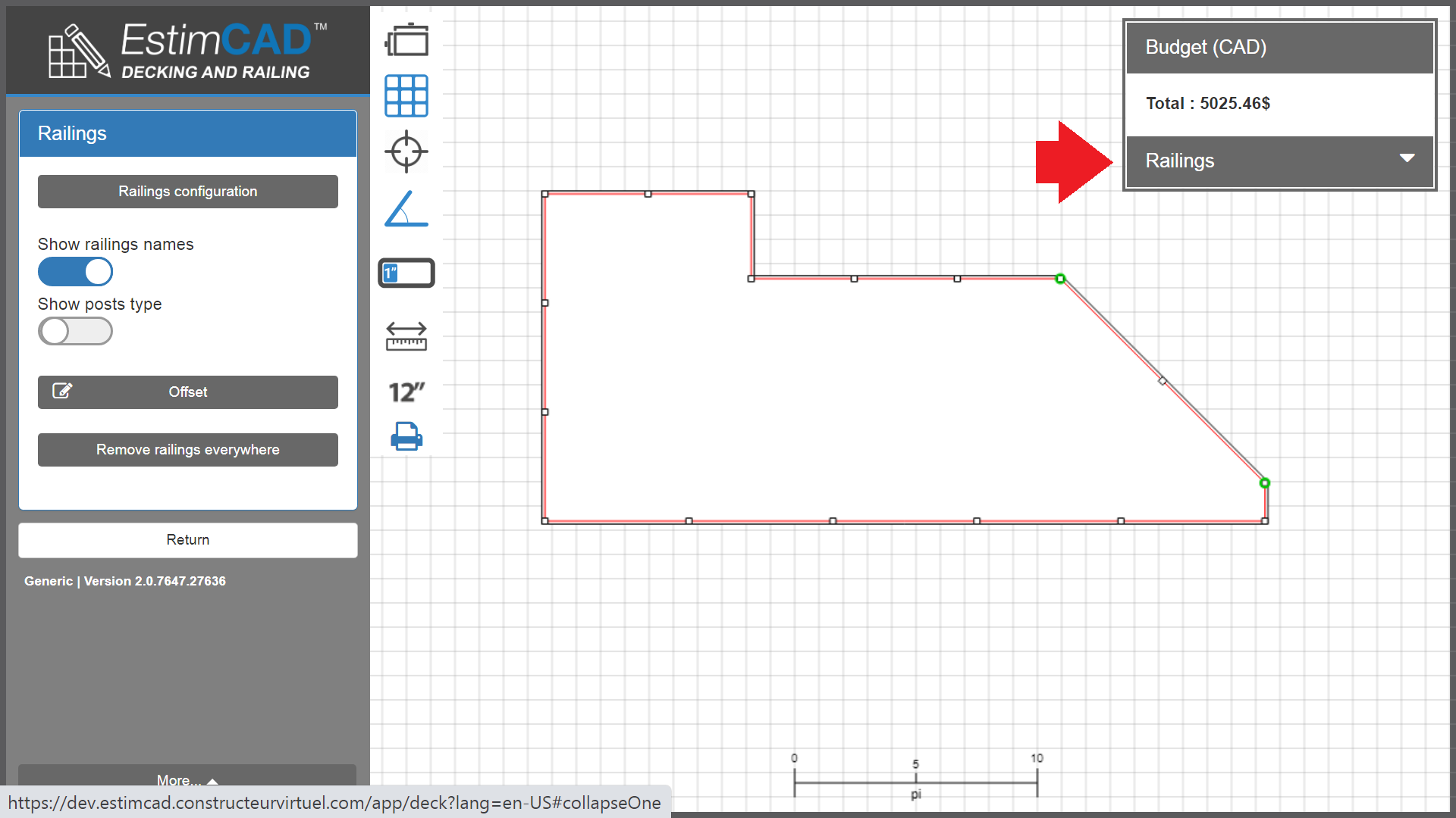
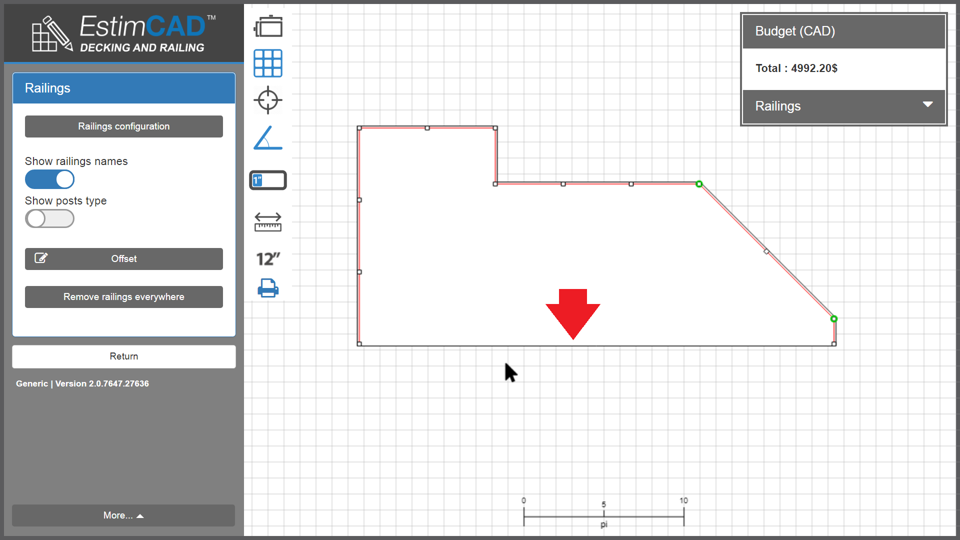
Here is an example explaining rail calculations with the following entered data:
Side length of the deck 10 ’- 3-11 / 16’ ’
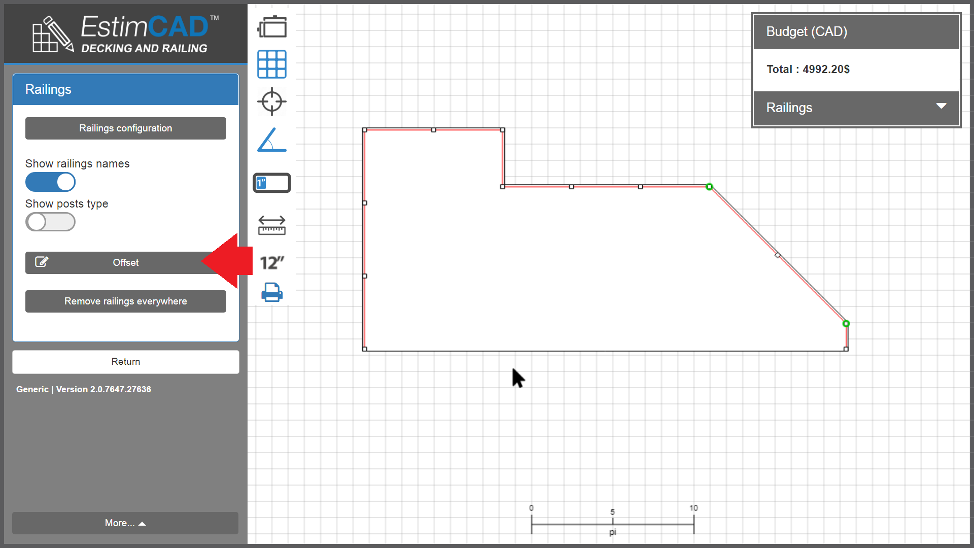
Applying a 2-inch Post Offset
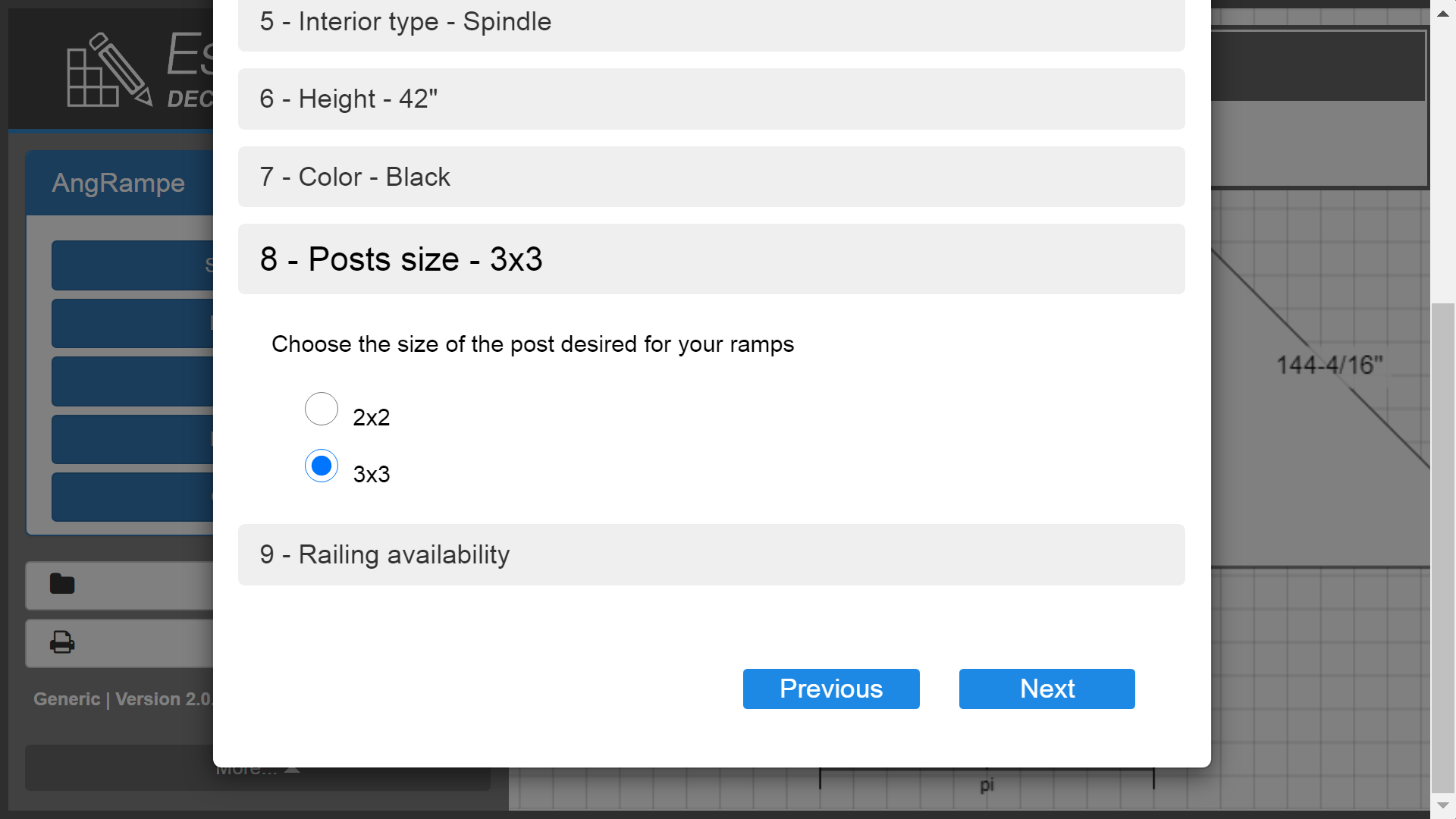
Selecting a 3x3 inch post
Selecting an R48 (48 '') rail
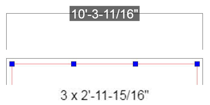
As shown above, the result will be 3 R48 interior post segments measuring:
2 ’- 11 - 15/16" or 35 - 15/16 "
In context. In the 8'-0 '' x 12'-0 '' plan below
. the posts are 3''x 3 "
. the selected rail is R46
. the offset applied everywhere is 2’’
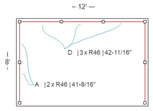
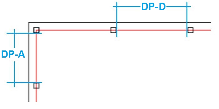
What is the distance between the posts?
This is the maximum interior length between the posts and not the center-to-center distance between the posts, in the image below, linked to the plan above
. the DP-A is 41-8 / 16 ’’
. the DP-D is 42-11 / 16 ’’
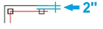
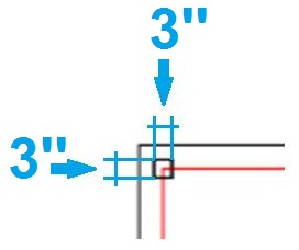
What is post offset?
This is the desired distance between the exterior deck and the exterior post (not from the molding at the base of the post)
In this example, the offset would be 2".
What is the post dimension?
This is the outside dimension of the post and not the dimension of the molding at the base of the post.
In this example, the dimension of the posts is 3 '' x 3 ''.
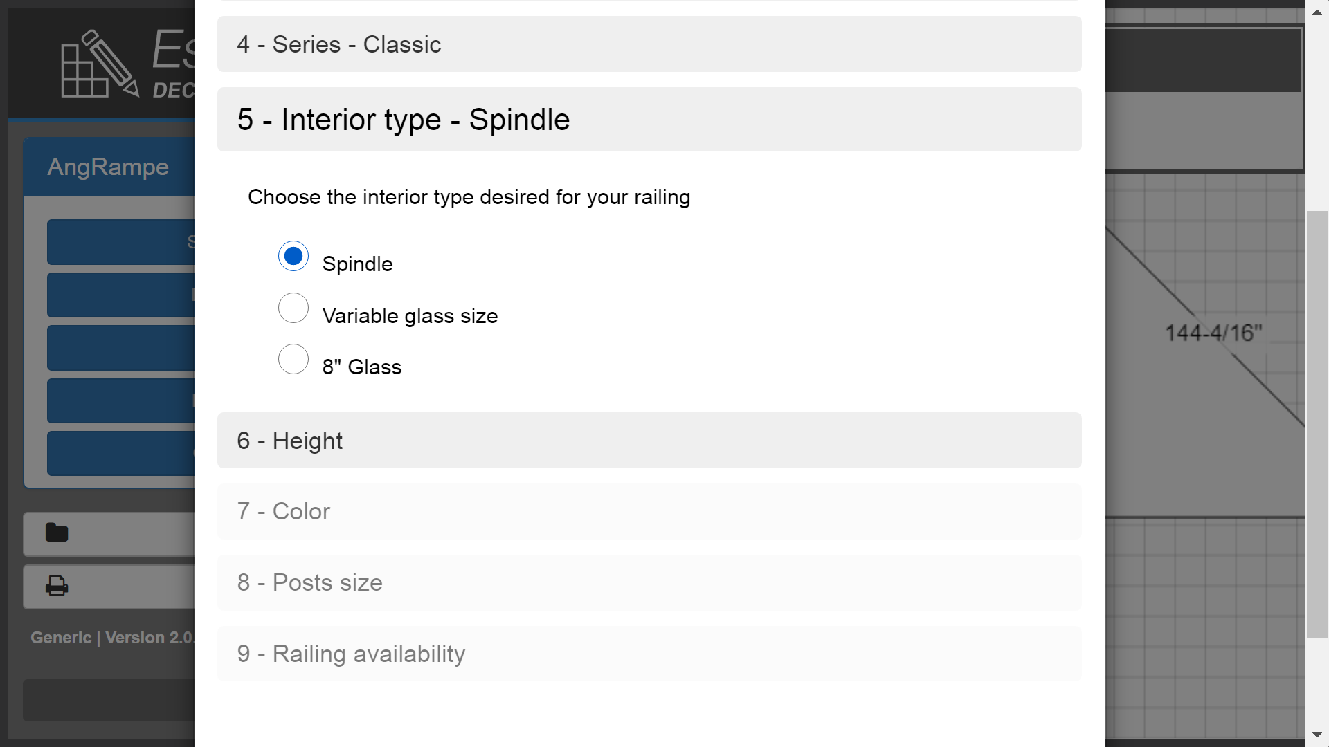
Railing with spindles
Here is an example of an estimated plan with spindles.
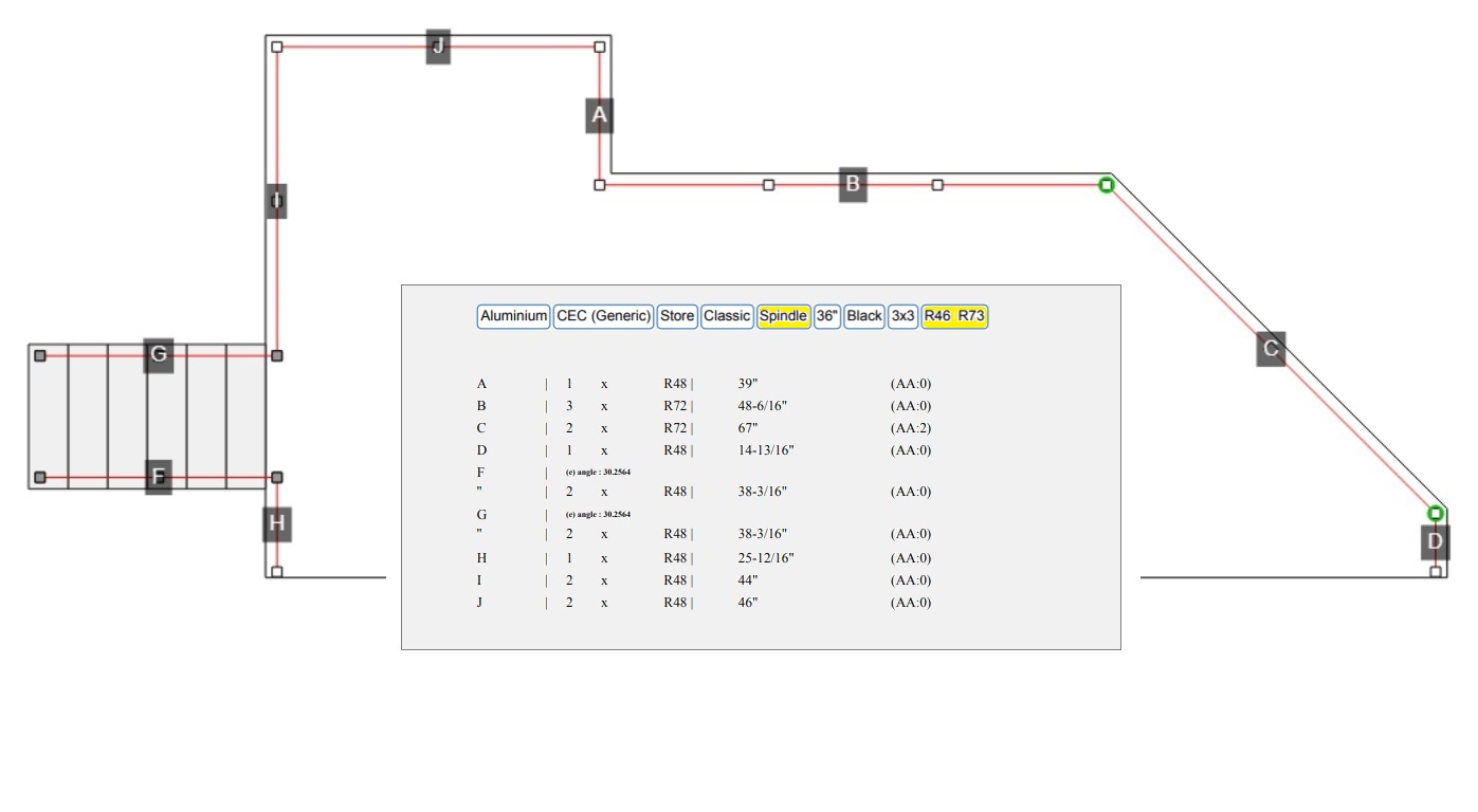
See the B side rail segments in the plan as shown above.
The app calculated 3 pre-assembled 72 "(R72) rails
to be cut at 48-6/16".
Railing with glass in variable sizes
Here is an example of an estimated plan with glasses of varying sizes.
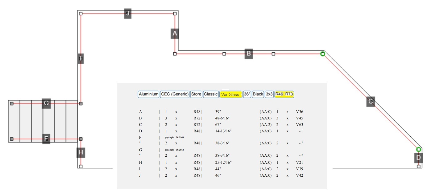
See the railing segments on side B in the plan as shown above. The app calculated 3 pre-assembled 72 "(R72) rails to be cut at 48- 6/16". The 3 glasses required inside each ramp will be 45 "(V45). So 3 R72 railings and 3xV45 glasses will be offered.
The calculations for these glasses display a slight spacing on each side of the posts. So measuring 48-6/16 "between the posts with a 45" glass will leave a space of 1.68"= 1-11/16" on each side. It is important to note that the glass railing models may be different from the spindle railing and the preassembled lengths available in store may not be the same.
Example, the inventory of spindle railings could be R48, R60 and R72. Unlike the glass railings of R48 and R72 only. So, it could be possible that the posts on your plan are not placed the same if they are for glass or spindles. See the rail segments on side B of the plan. Note that the glass R60 are not available (unlike the spindle rails) so the application calculated R72.
Sometimes it is also possible that the glasses are not available for the stair rails. You will then have to choose to install railings with bars or to make a special order from the manufacturer. On the plan above, railings F and G are not available in glass.
8 '' Glass Railing
Here is an example of an estimated plan with 8'' size Glass Railing
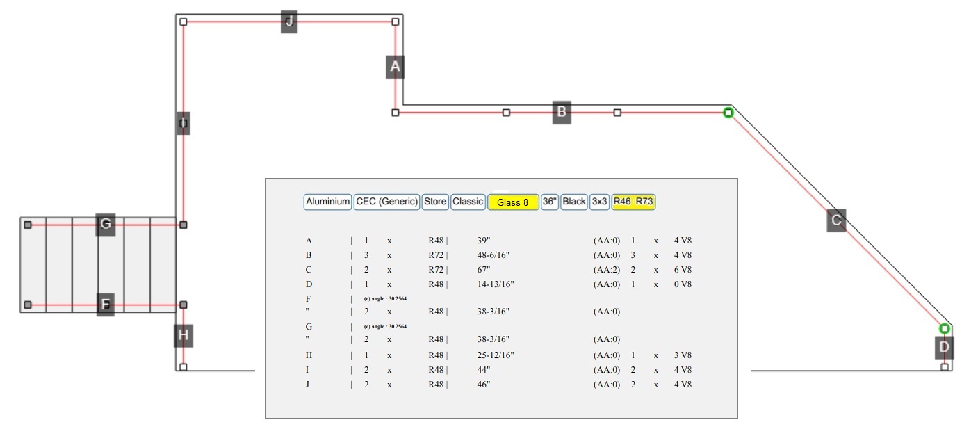
The app calculated 3 pre-assembled 72 "(R72) rails to be cut at 48- 6/16". The glasses required inside each rail will be 4 x 8. So 3xR72 rails and 3x4-V8 glasses will be offered.
The calculations of these glasses allow a slight spacing on each side of the posts. So measuring 48-6/16 " between the posts with 4 glasses of 8" will leave 5 spaces of 3.275 "= 3-4/16" between each glasses and posts.
It is important to note that glass railings may be different from spindle railings and the pre-assembled lengths available in store may not be the same.
The inventory of spindle railings could be R48, R60 and R72 but that of glass rails of R48 and R72 only. It might be possible that the posts on your plan are not placed the same if they are for glass or spindles. See the railing segments on side B of the plan. Note that the R60 in glass are not available (unlike the spindle railing) so the application has calculated R72.
Sometimes it is also possible that the glasses are not available for the stair railings. You will then have to choose to install spindle railings or to make a special order from the manufacturer. On the plan above, ramps F and G are not available in glass.
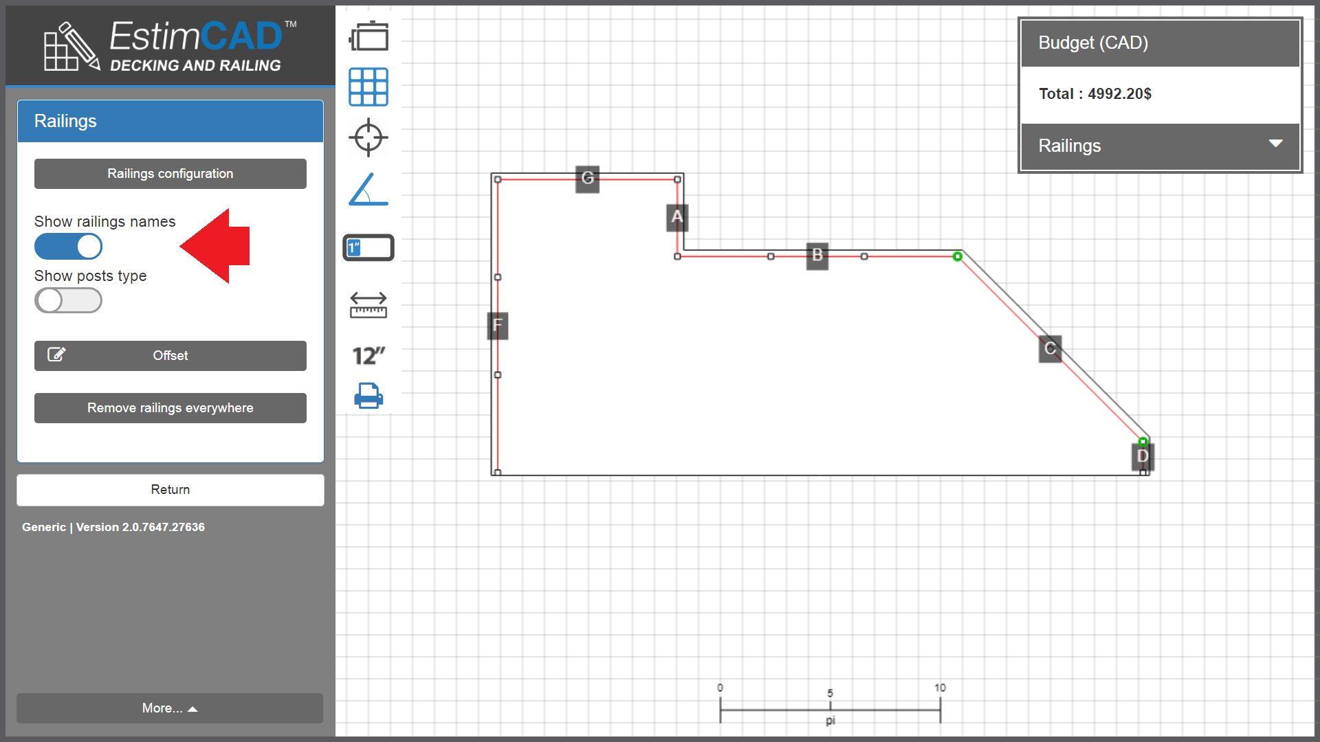
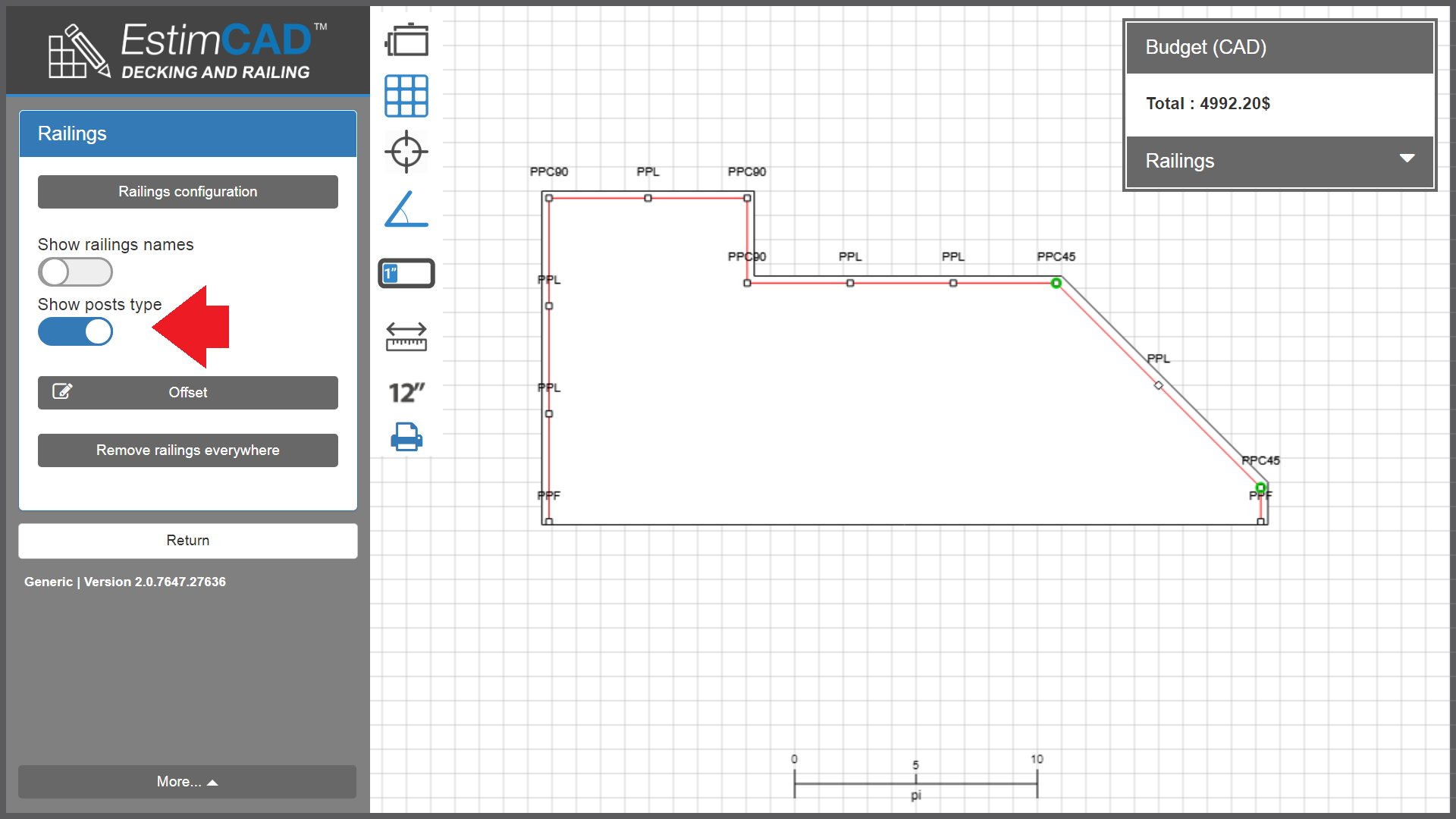
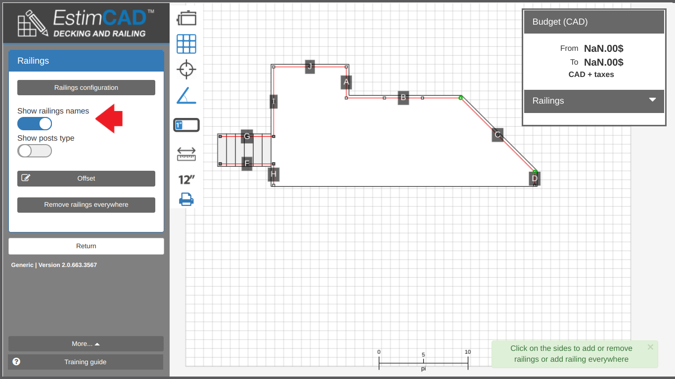
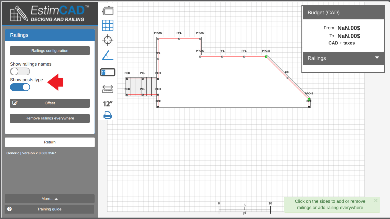
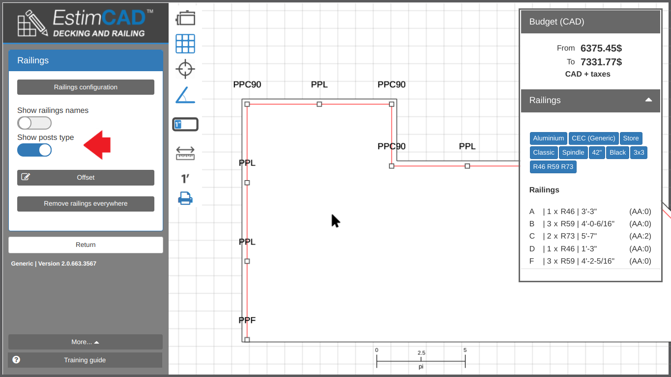
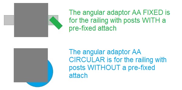
If posts have fasteners that are attached in a factory, post identifiers (IDs) are required and should be shown on the plan.
If posts do not have factory-attached fasteners, post identifiers (IDs) are optional and may not be shown on the plan.
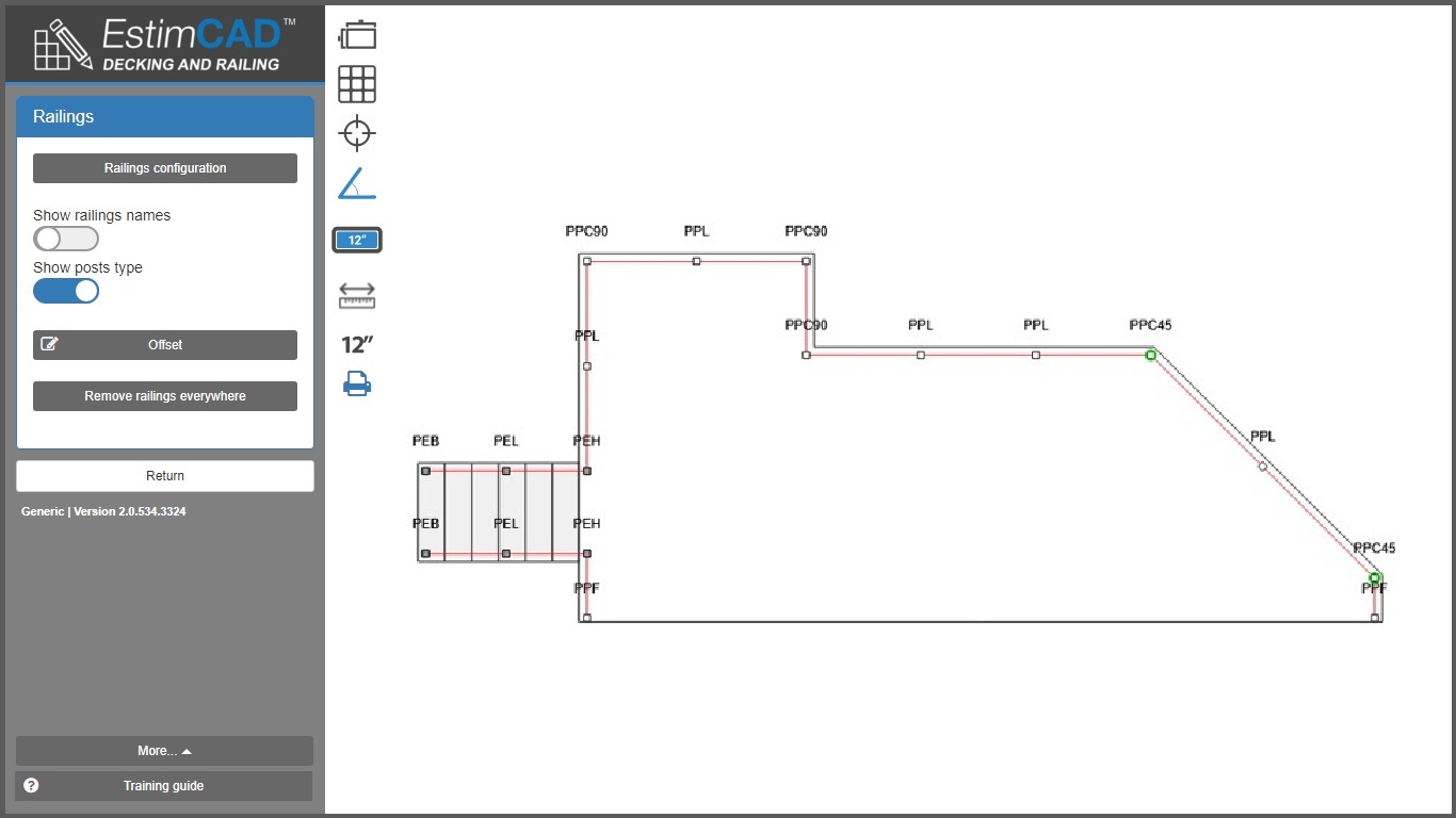
Above, plan with post identifiers ID
Below, post identifiers ID
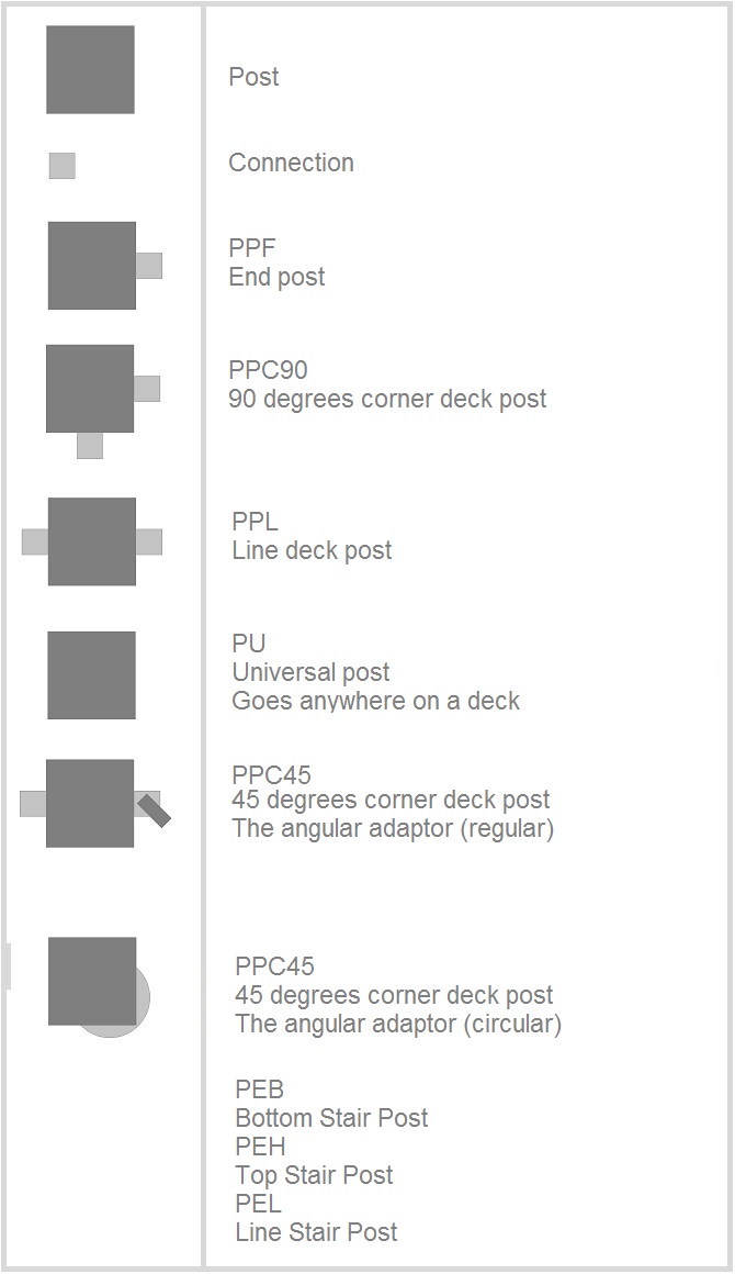
AA definition
The angular adapter (AA) is an accessory part which is fixed on a post to receive a railing. This makes the joint between the railing and the post when there is a 45 degree angle.
The application automatically adds the angular adapters (AA) which are illustrated by a green circle around a post on the plan. And they are identified by the letters AA in the product list.
Angular adapters (AA)
AA geometry
Understanding the geometry of angular adapters (AA)
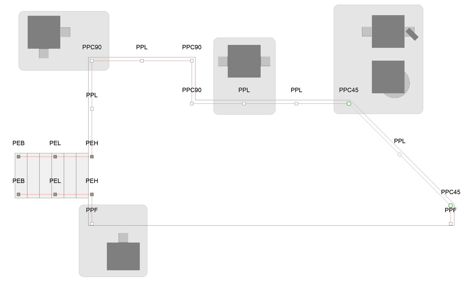
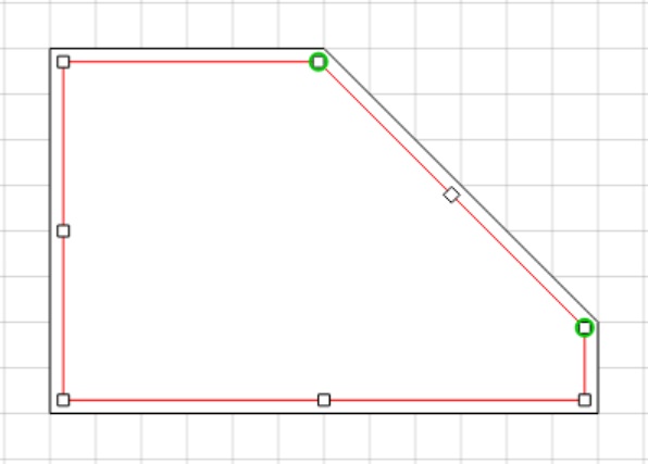
The orientation of a post is determined according to the direction of one of the two lines adjacent to this post for which a single AA is required.
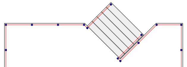
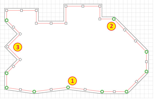
Note that in the plan below, each junction of red lines with a green circle requires an AA and those without a circle do not. This plan therefore requires a total of 10 angle adapters (AA).
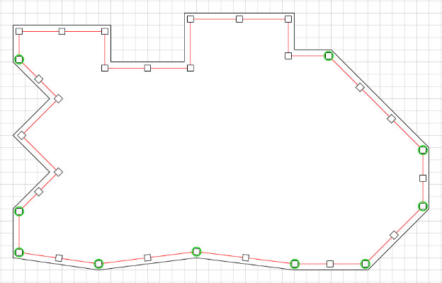
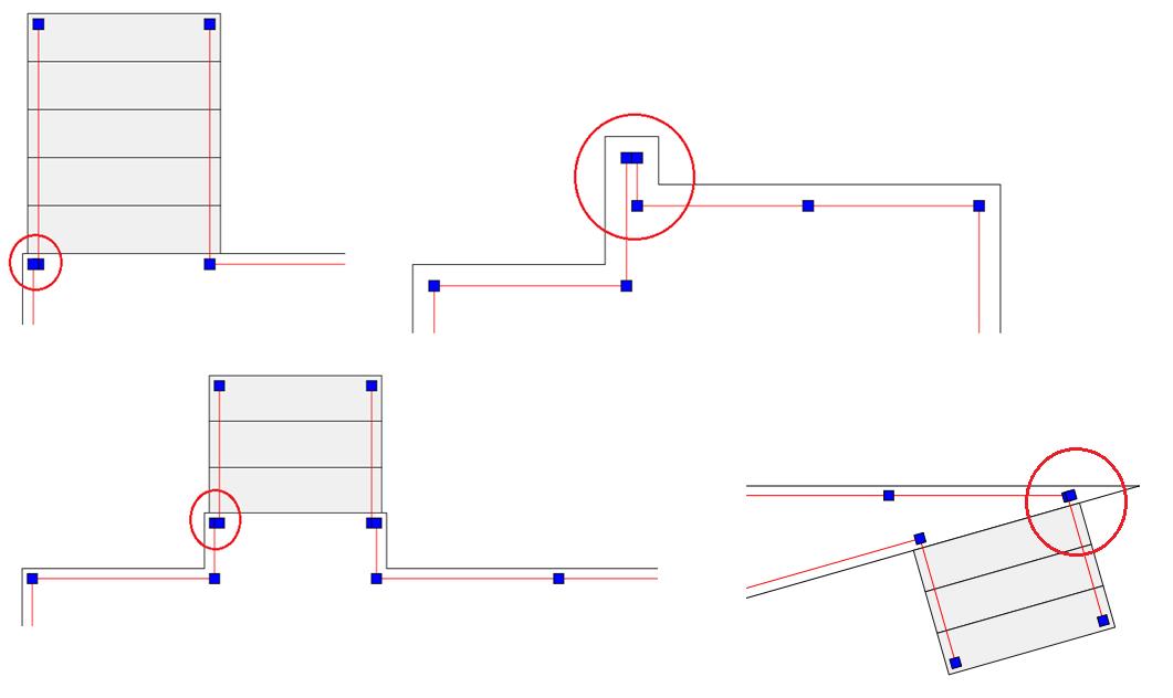
We have considered the horizontal (X) and vertical (Y) axes as being the 2 main axes that the posts must follow. If none of the lines adjacent to this post follow these axes then the post takes the direction of the line drawn previously.
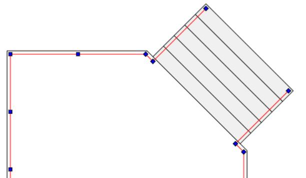
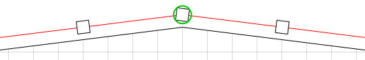
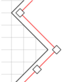
Below, the direction of the post follows the angle of the previous line. This is because there is no right angle (90 °) and no line along the horizontal or vertical axis. Only one AA is required.
Below the post is forced to be horizontal because one of its two adjacent segments is on the horizontal axis. Only one angle adapter is required.
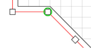
Below, the direction of the post follows the angle of the previous line. The angle between the two red lines is a right angle (90 °), so even if neither of the two segments is on one of the main axes, no angle adapter is required.
Circular or attached shapes AA
Two types of angle adapters (AA) are normally available from merchants.
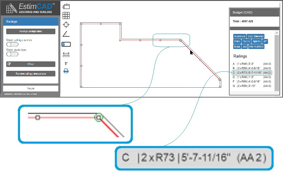
The plan below shows railings attached to posts where there are two 45 degree angle adapters (AA) represented by a green circle.
When the user wants to estimate a project where his plan has angles, he will have to choose one or the other of the following two calculation methods:
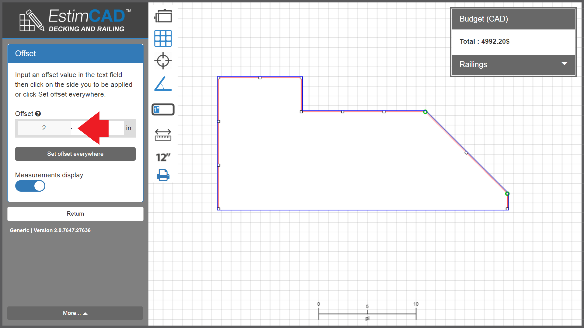
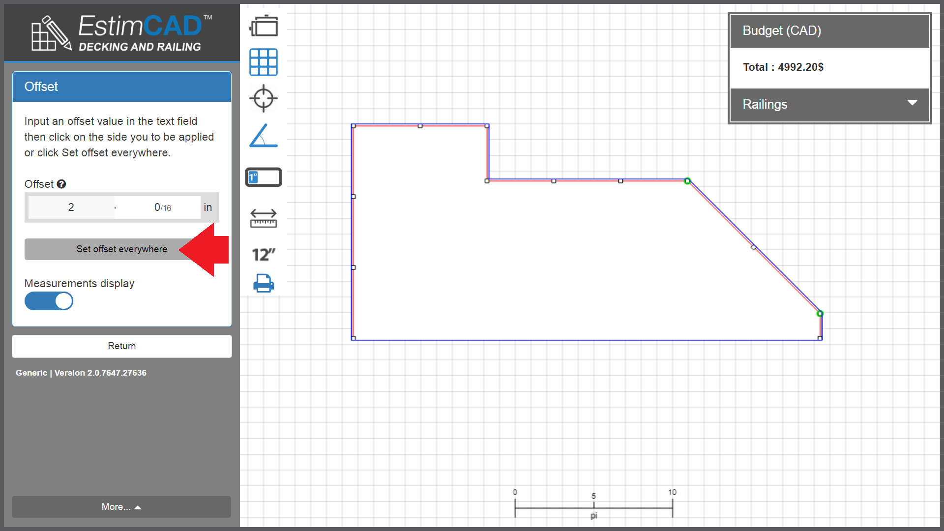
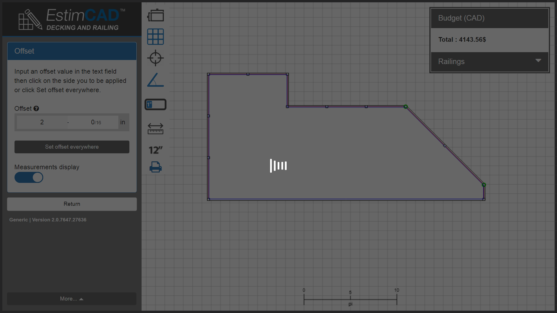
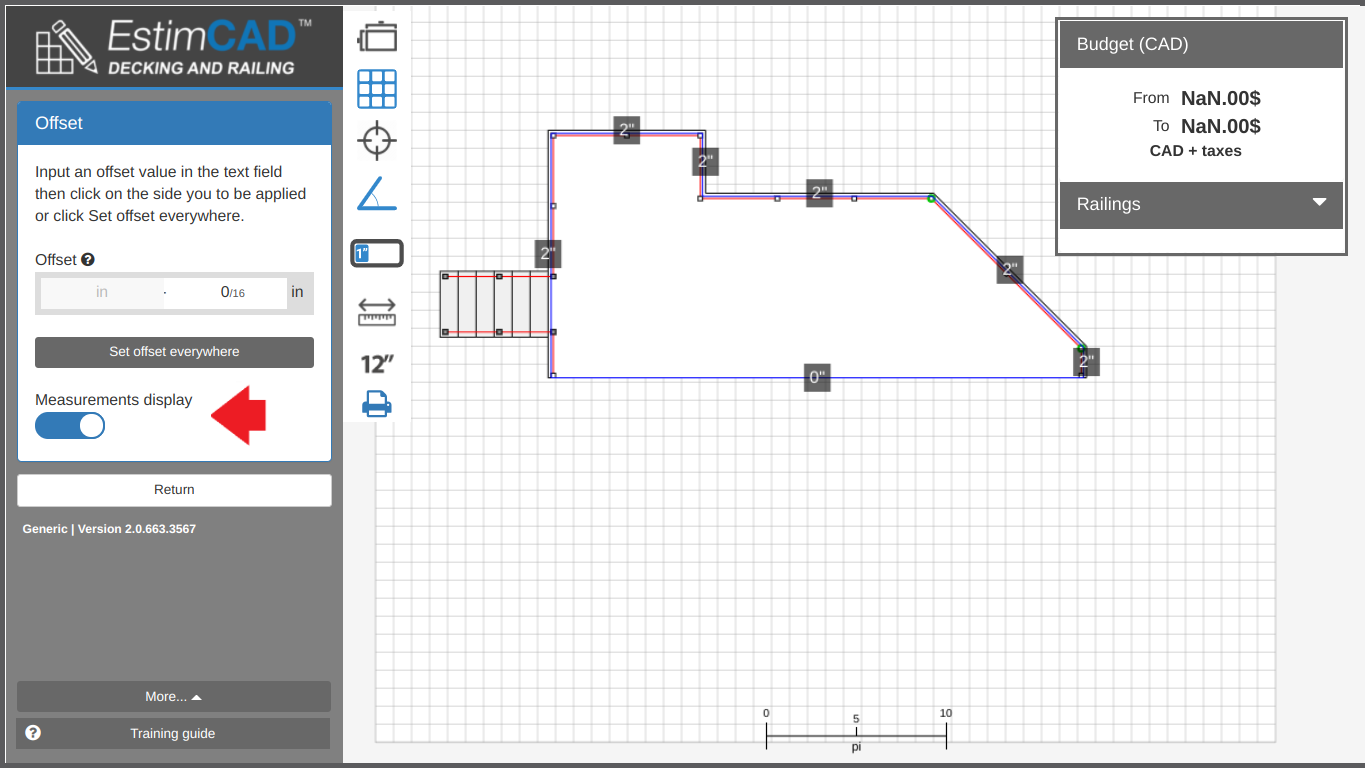
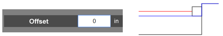
Calculation method # 1 : Symmetrical offset of the railings
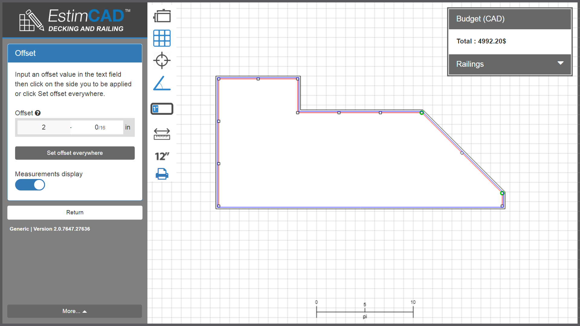
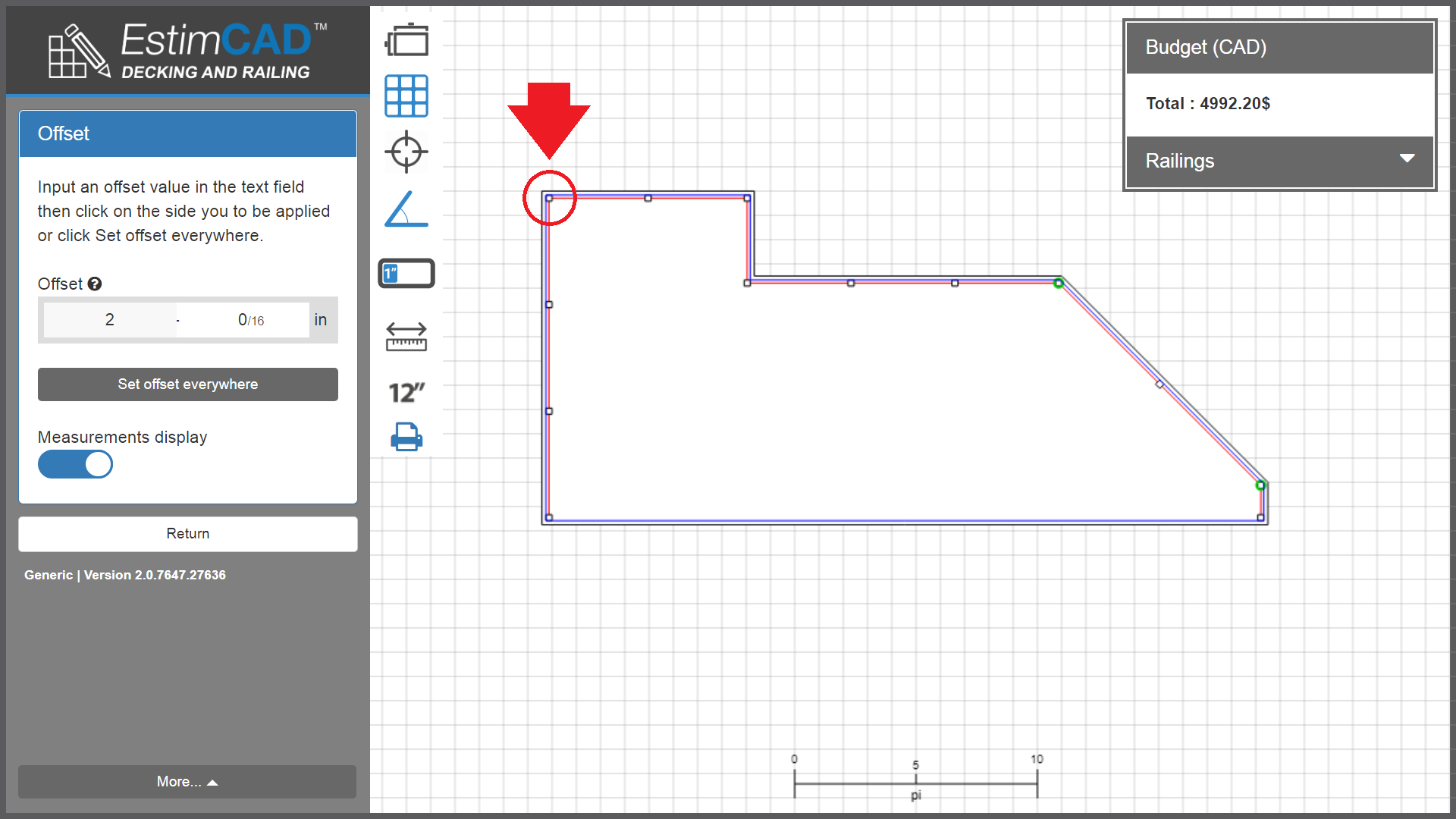
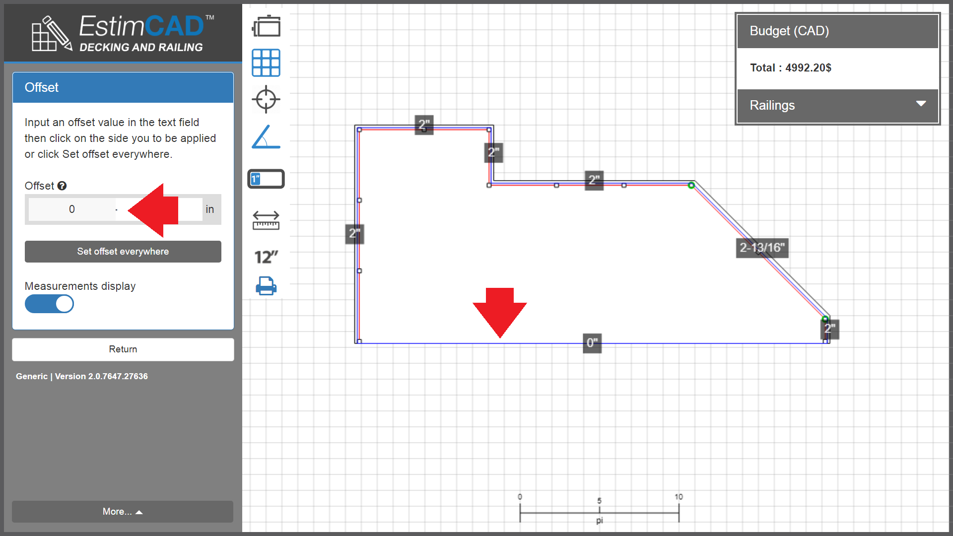
The images below illustrate the symmetrical offset of the railings. Note that the measurement assigned is 2" in this example. And this, everywhere on the plan.
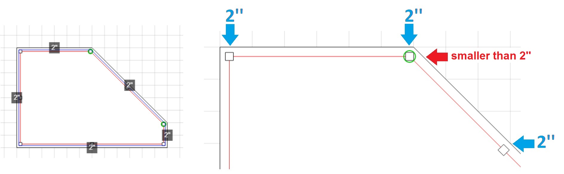
Note that the post offset measurement with angular adapters (AA) such as the one circled in green above will be less than 2 inches on the 45 degree angle side.
Calculation method # 2 : Symmetrical offset of the 2 posts with AA
The image below to the right shows the symmetrical offset of the posts with angular adapters (AA) whose assigned measurement is 2" in this example.
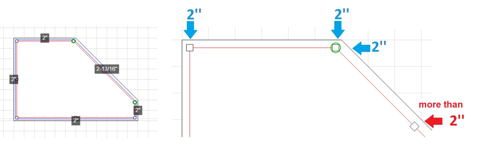
Note that the railing offset measurement, which angle is 45 degrees, will be greater than 2 inches.
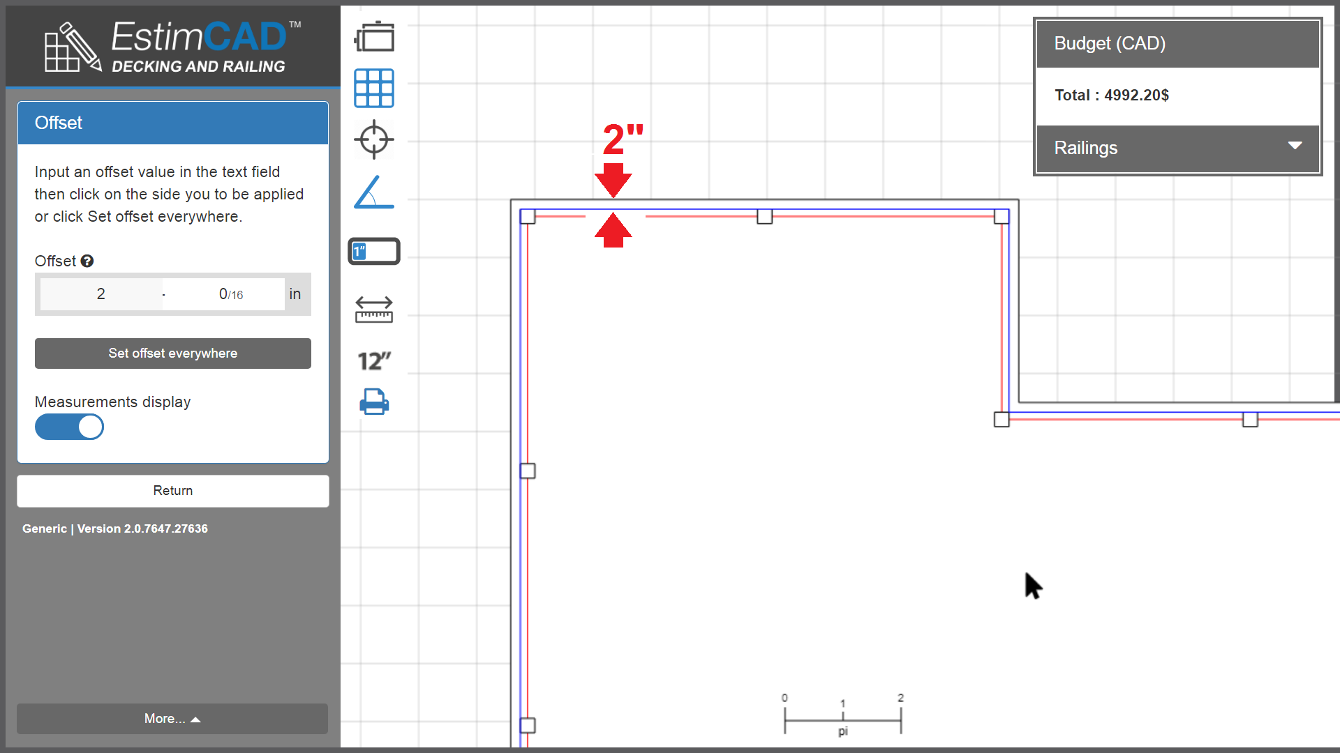
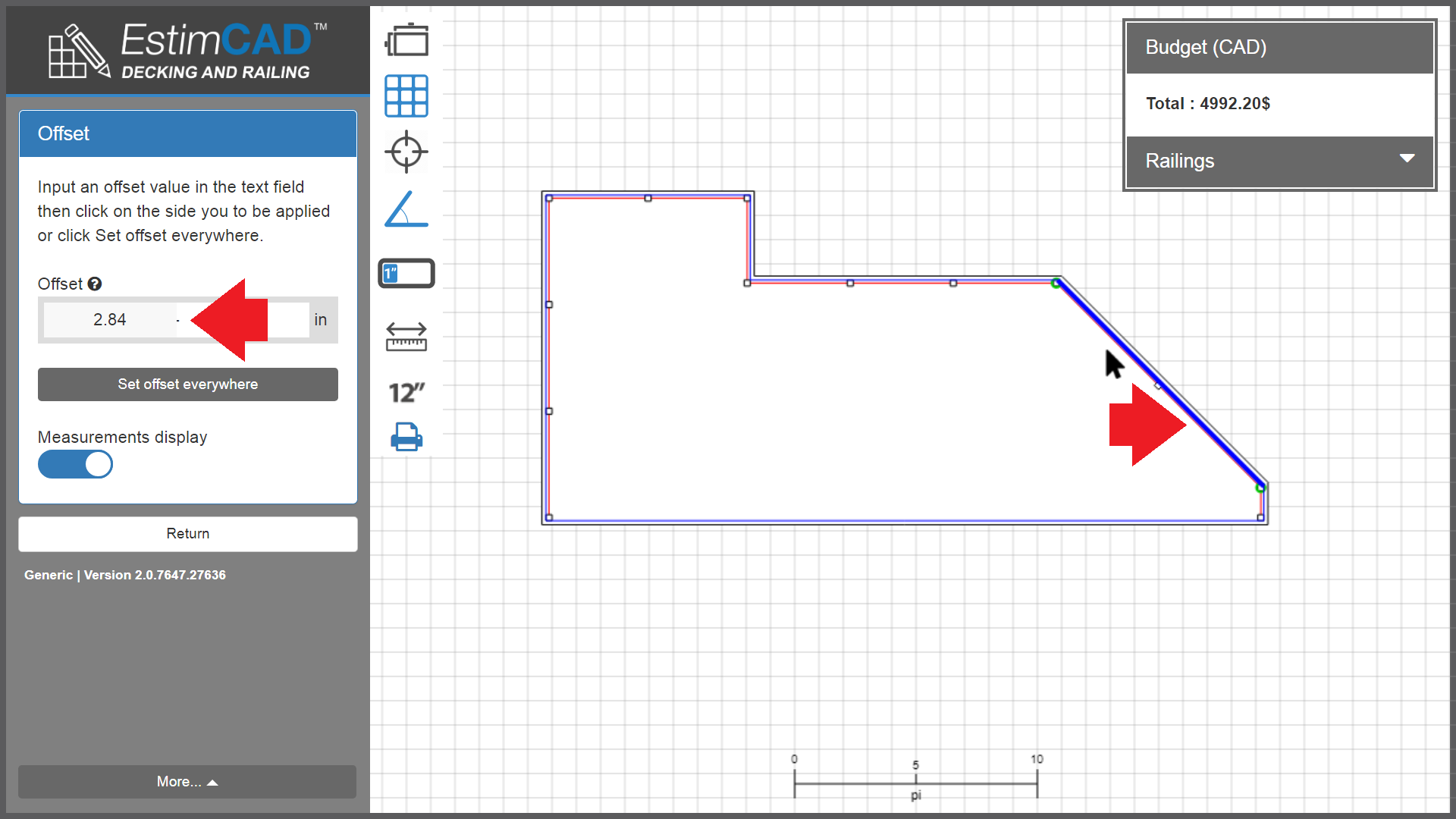
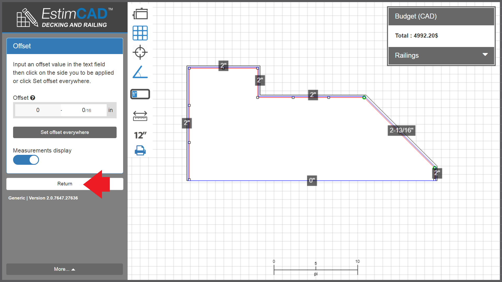
Step 1: 2 '' offset everywhere
Step 2: offset 2 - 13/16 " to the side at a 45 degree angle
To obtain this result,
multiply the normal offset measurement of 2" by 1.42
to give 2.84" or 2-13/16 "as shown in the image above on the left.
In other words, 1.42 is a constant with which the user always multiplies his offset (which is applied everywhere) except on the angle.
So if the offset would be 3" everywhere,
then the user will put (3 x 1.42 =) 4.26’’ on the angle.
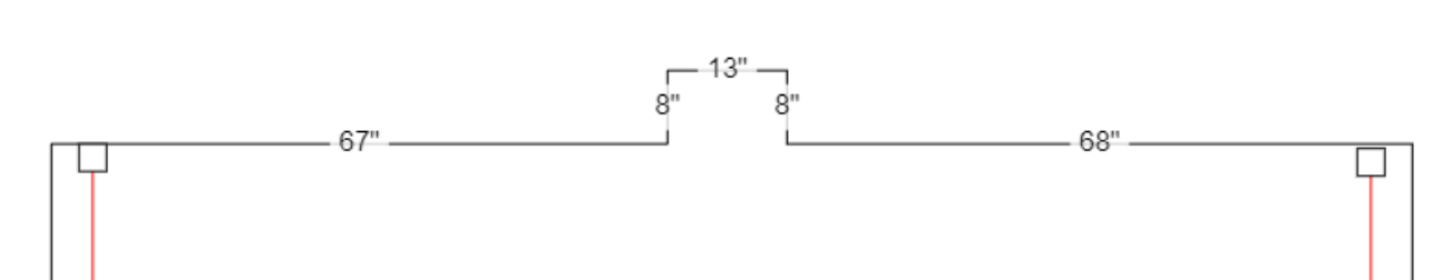
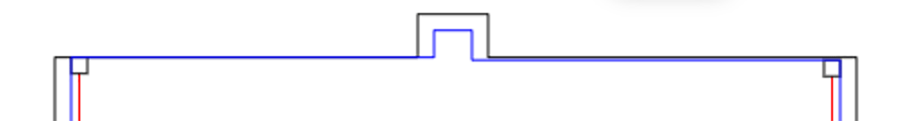
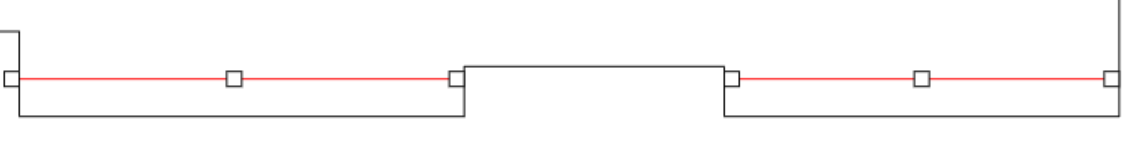
To apply more than one offset to a wall you will need to make a notch in the wall side while drawing the deck. This notch will enable you to just set different offsets on the parts on each side of it.
The application has been built to respect the mathematical representation of a deck.
For exception cases, Mathematics can sometimes yield an undesired result and therefore you will need to manually adjust the results for those cases.
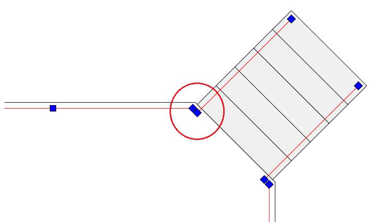
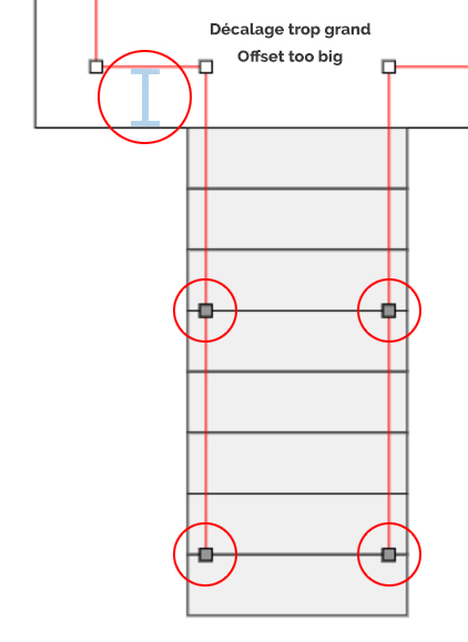
In the example below, the posts in the upper right, circled in red, seem problematic, but this plan respects math logic.
You will need to either change your desired railings offset or adjust it manually after the calculations.
That means you will need to give contractors different lengths than what is calculated by the software.
It works the same way for the following impossible cases. You need to make adjustments after our calculations or change the settings of the deck. The software does now manage these issues.
The image below illustrates that the posts at the end of right angled segments where there is an angle stay straight with the other posts in-line.
Therefore, only the interior posts of the angled segments will follow its angle.
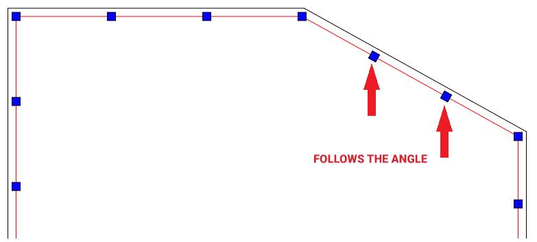
The adjustments of the angle cuts of the railings will be done on site at installation.
You will need to calculate this specific railing length because the software does not take it into account.
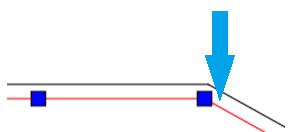
In the case where we apply a 0" offset to align the posts with a wall, if the adjacent segment to the wall is an angle, the corner post will turn when we remove the railing on the wall side, but in this special case we probably want it to stay perpendicular to the wall.
To calculate the railings adjacent to the wall correctly, do not remove the railings on the wall and remove it from the calculations manually. This will prevent the corner post from turning.
You can change the orientation of your beams and joists. The system computes an optimized solution to obtain the least amount of piles, beams and joists possible to have the best price while still respecting the building codes.
You can also move the beams yourself to create your own solution or to avoid an obstacle.
Click on « Move the beams ». Then, click and hold on the plan and drag to watch your structure recalculate.
You can identify sides of your deck as supported by a house or any other structure.
To to so, click on « Identify » in the Building Sides section of the Structure menu. While « Identify » is active, click the sides to designate them as externally supported. When you are satisfied with your choices, click on « Identify » again.
The application automatically offers optimized solutions. This means it calculates all possible solutions while respecting construction norms and outputs the best of them all to minimize costs and loss. Let’s take a look at these three configurations for the same simple project :
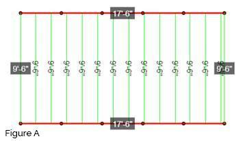
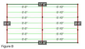
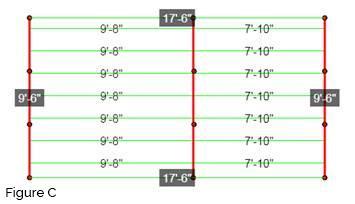
The optimal solution for this project is image C with a total cost of 1315.05$. The image A has a total cost of 1351.98$ and has too many beams and image B has a total cost of 1334.51$ and introduces too much material loss in the joists.
It is easy to think about this reasoning being simple on a simple project like the one above, but the complexity rises exponentially when you apply it on a project like the images below.
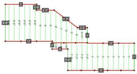
Now we need to ask ourselves about the desired structure. An optimal solution might be more complex than a simpler structure with more loss. A client with a contractor can present him multiple solutions to then get enlightened on the proper decision. You can also move the joists manually to create your own solution.
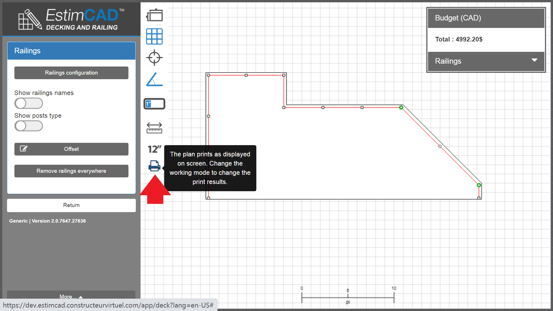
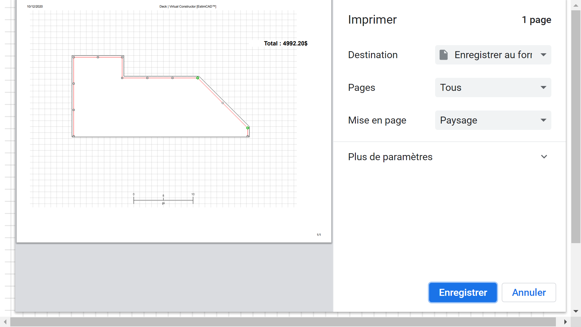
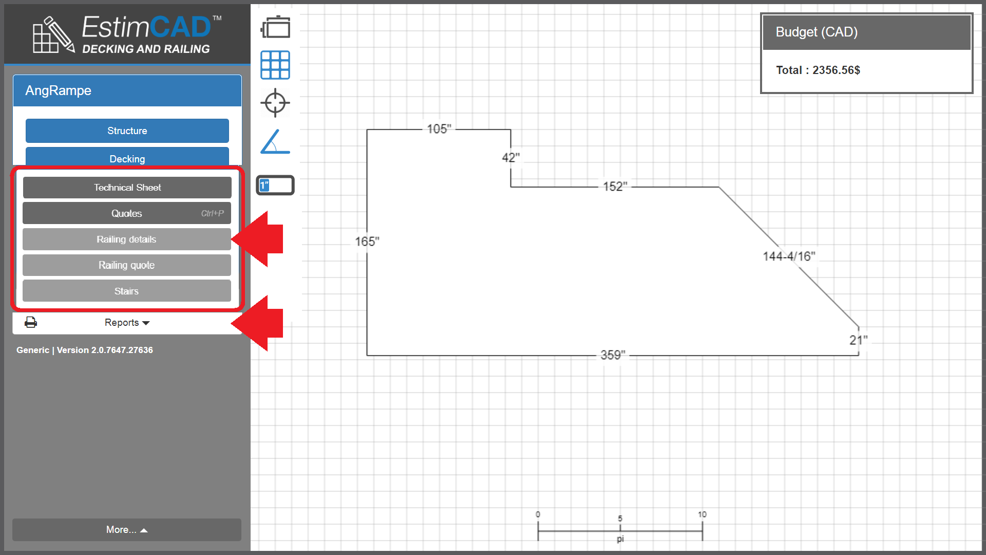
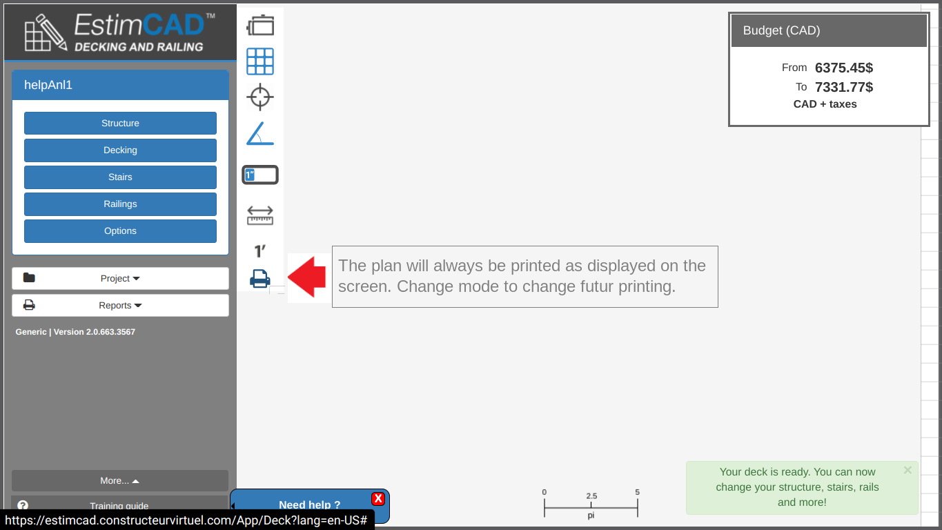
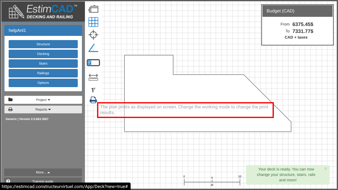
To understand the print of plans and reports you need to do this TRAINING on Print the results of a client file
It is possible to calculate the railings in a deck project that has columns and/or gates, but you have to ask us the key that allows you to use this function for expert only at support@estimcad.com . However it requires a little bit more preparation because the positioning and dimensions of the columns and gates must be known before the drawing starts.
Doing this invalidates the deck structure calculations
We will start by explaining the concept with construction lines, but we do not recommend using this technique as it is quite slow and does not offer 1/16" precision.
Let's visualize a deck that is 133" by 92" and has an existing column.
The column is 9" by 12" with offsets of 2" and 3" on the side and bottom respectively.
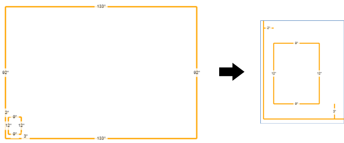
From that, we can draw an outline excluding a notch for the column, allowing the application to calculate the railings as desired.
As you can see, we added the dimensions of the column to its offset and made a notch in the outline. That is why you need to know the columns dimensions and positioning before drawing.
With some practice, this technique becomes intuitive, no longer requiring construction lines, increasing speed and precision greatly.
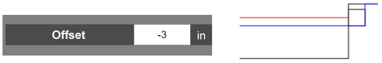
In the next image we illustrate hiding the posts within the column by applying negative offsets to the columns sides.
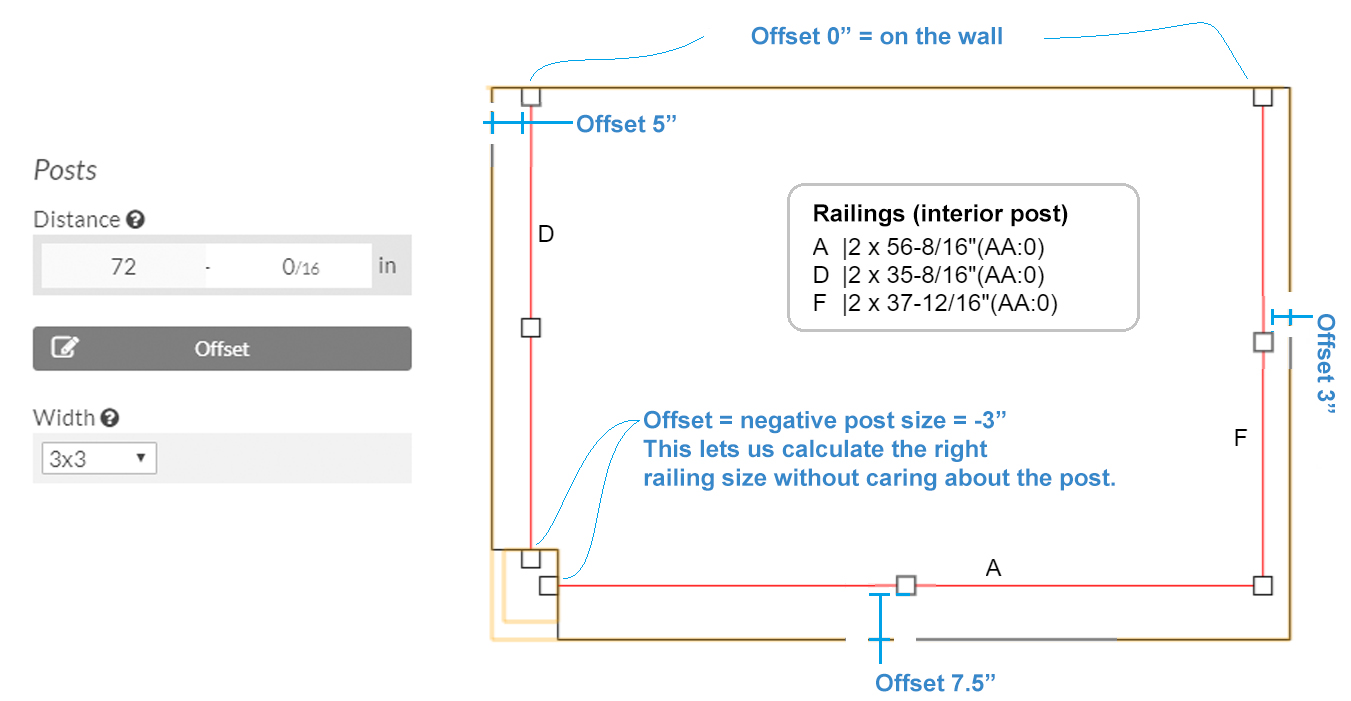
Hiding the posts this way allows you to calculate the proper railing lengths to get railings up to the column. Since we had 3" posts, we are simply applying a negative 3" (-3") offset.
The following video is currently only available in french. Sorry for the inconvenience.
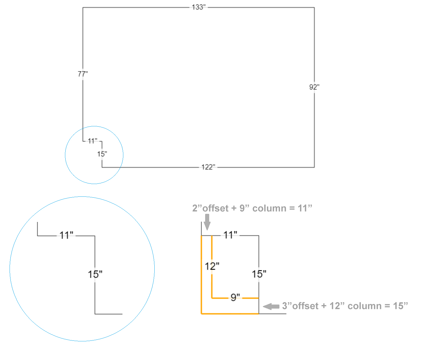
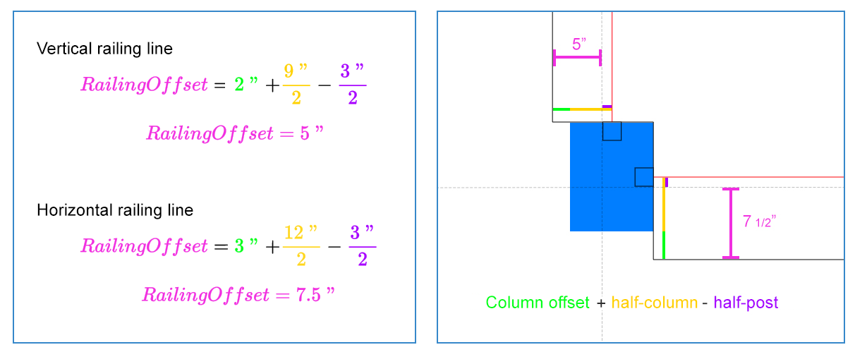
If you'd like to center the railings on the column you'll need to figure out the proper offset to apply. To calculate that, we made a simple formula :

Applied to our example :
If we want to stick a post to the column we can put a 0" offset to the columns sides or we can apply a negative offset equivalent to the post size to calculate the proper interior post railing size.
If you hide the posts using this technique you will need to manually remove them from the materials list the application will give you. The application does not adjust quantities automatically in this scenario.
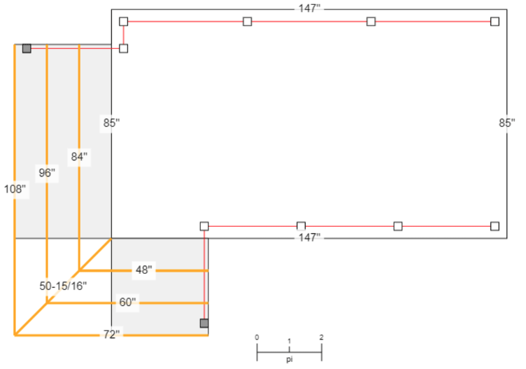
The concept stays the same with multiples columns or even mixing in columns and gates.
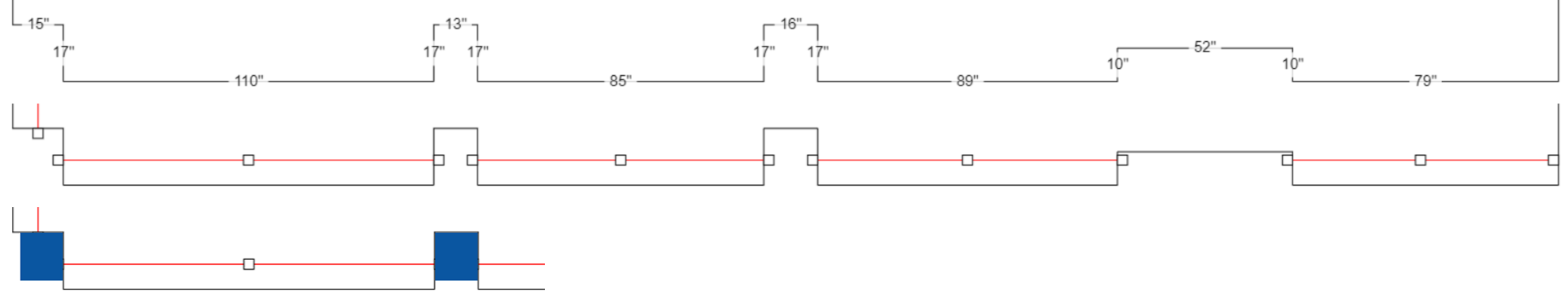
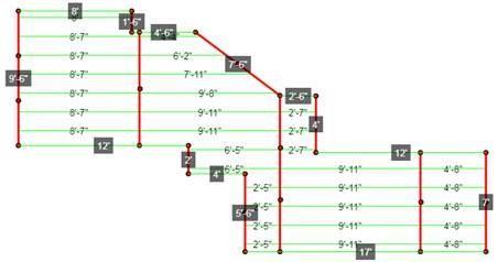
In this example we have not centered the railings on the columns and we assume that all columns have a uniform offset of 2".
Let's not look at vertical (Y) measurements, we can assume they are all 15" deep and have a 2" offset, giving a (15" + 2") = 17" offset.
So now let's take a look at the horizontal (X) measurements.
From left to right:
Depending on the gate product available, you may want to calculate the gate with interior or exterior measurements.
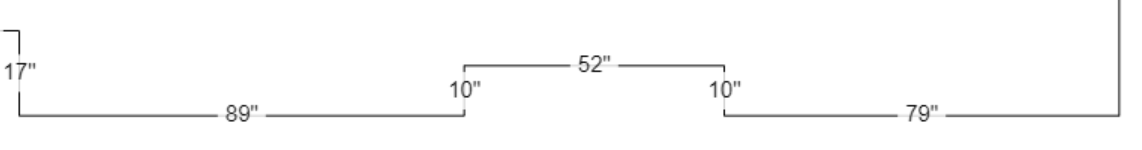
In the following image, the 52" gate hole is considered exterior gate posts :

To achieve this :
In the image below the 52" gate hole is considered interior gate posts :
To achieve this :
The techniques to deal with columns are all just tips and tricks and are not officially supported by the application yet. This means there are some restrictions to follow in order to stay accurate and have a good result.
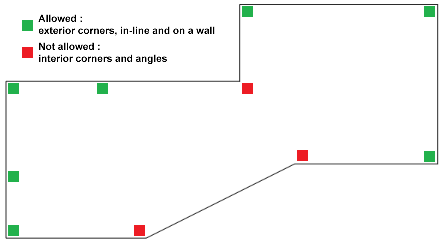
The columns and gates placement MUST abide the following placement rules. The application simply cannot calculate columns in the red positions with the aforementioned techniques.
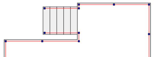
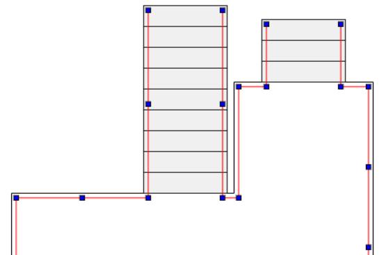
To imitate corner stairs you just need to place 2 separate stairs on the corner. Afterward, trace along the lines like the image below :
This will allow you to calculate the length of the 2"x6" required for the steps, therefore you'll need to add them manually to the quote.
This method does not calculate the structure under the steps in the corner. You need to think about adding structural elements to the quote manually to make the structure in the corner and respect building code.
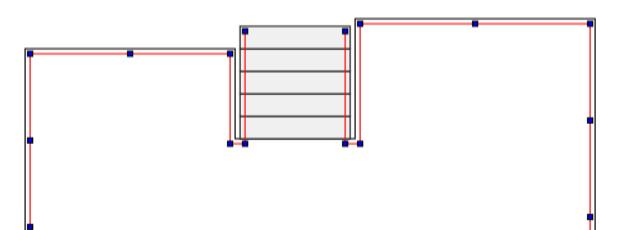
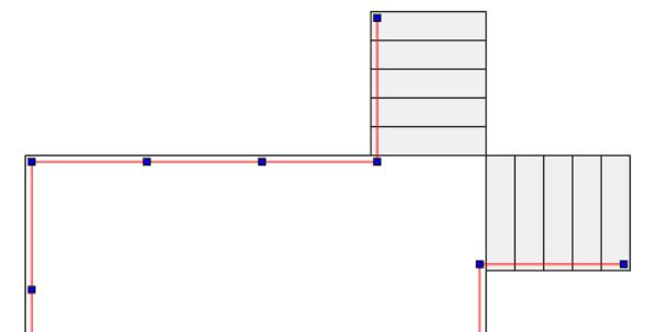
You will need to make two plans separately. Make plan 1 and save it. Then to make plan 2, you must place the arriving stair set from plan 1 precisely where it was with the same settings.
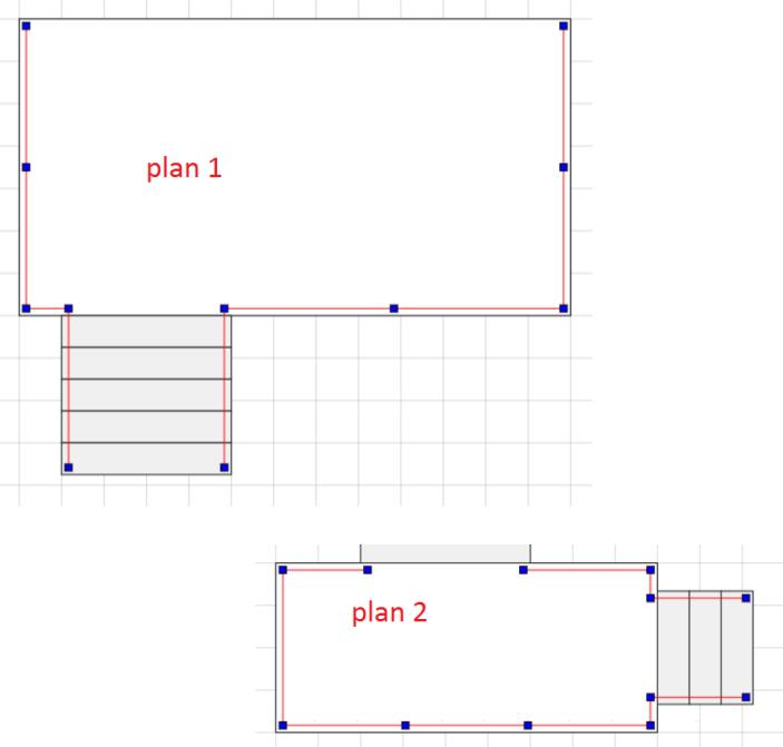
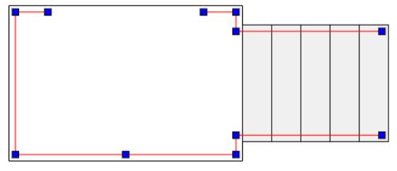
If we overlay these plans on top of each other they will match perfectly like the plan below, because the measurements of the stair set between decks are identical on both plans. The placement is also very imortant, so be precise in both plans.
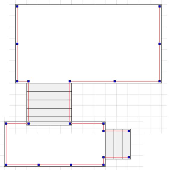
This image is the result of using graphic software to overlay both plans on top of each other.
The following video is currently only available in french. Sorry for the inconvenience.
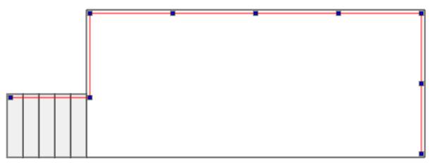
You will still need to close your outline even if your real project does not work that way. You only need to add segments preferably at right angles to close the outline and then not add any railings to it. If there needs to be an opening, you might have to think about your planning a little bit more.
The user of the EstimCAD ™ Deck and Railings application can be either a consumer, a hardware store / materials dealer, a general or specialized contractor or a manufacturer of aluminum or glass railings, it is imperative to understand the concepts that are described in this guide and to do exercises to make sure you have an experience that results will be simple, easy and quick to achieve while minimizing the risk of error.For any questions or comments please do not hesitate to contact the EstimCAD ™ Application for Patio and Ramps Customer Support team at: support@estimcad.com .
-